|
| |
TM 10-4210-235-13
2-9. ASSEMBLY AND PREPARATION FOR USE. - continued
(10)
Check that the system valves are In the proper ready state position.
(a)
Both purge ball valves (1) should be CLOSED. Strip ties (2) In place
(b)
Both charge ball valves (3) should be OPEN. Strip ties (4) In place
(c)
Valve rods (5) should be CLOSED.
(d)
Both nitrogen cylinder valves (6) have two each strip ties (7) in place
b.
Installation.
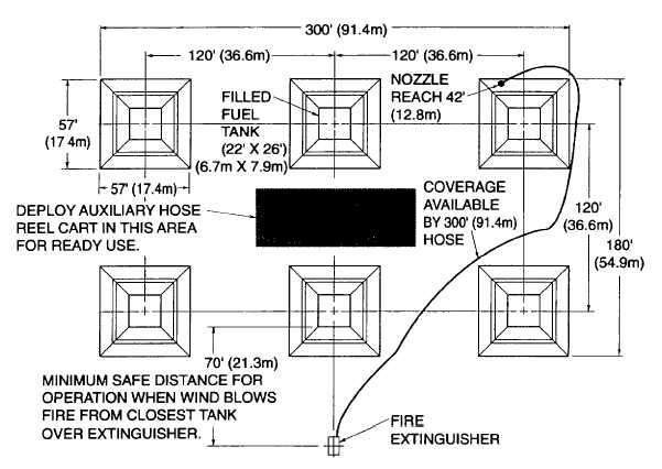
Figure 2-9. Location of Trailer Mounted Fire Extinguisher and Auxiliary Hose Reel Cart
(1)
Site selection.
NOTE
Figure 2-9 is a typical installation configuration. See system manual for additional
configurations.
(a)
The trailer mounted extinguisher assembly can be used as a portable unit being towed or set-up for
stationary use. The unit does not need to be precisely leveled. Refer to figure 2-8 for recommended locations with
respect to bulk fuel tanks and auxiliary mobile hose reel cart to provide safety of operation and maximum effectiveness
2-36
|