|
| |
TM 5-4210-220-34
2-21.
FRONT AXLE.
2-21.1 Ball Socket Assembly.
This task covers
a.
Removal
b.
Inspection
c.
Installation
TOOLS
Applicable Front Wheel Removed
Shop Equipment, Automotive
(see TM 5-4210-00-220-12)
Maintenance and Repair,
Axle Drained of Oil (see LO 5-4210-220-12)
NSN 4910-00-754-0705
Applicable Brake Assembly Removed
(see TM 5-4210-00-220-12)
EQUIPMENT CONDITION
Applicable Wheel Hub Removed
Main Engine Shutdown
(see TM 5-4210-22Q-12)
(see TM 5-4210-220-12)
Applicable Axle Shaft -removed
APU Engine Shutdown
(see TM 5-4210-22, 1472)
(see TM 5-4210-00-220-12)
Applicable Tie Rod End Disconnected (see TM
Batteries Disconnected
5-4210-00-220-12)
(see TM 5-4210-00-220-12)
Rear Wheels Blocked
MATERIALS/PARTS
Air Tanks Drained
10, Appendix B Dry Cleaning Solvent
16, Appendix B Grease
NOTE
This procedure is applicable to both left and right ball socket assembly
The ball socket assembly can only be replaced by replacing the individual components making up the
assembly. Removal, inspection, and installation of these components are detailed in this procedure.
REMOVAL
NOTE
To remove left hand ball socket assembly, it is necessary to remove steering drag link from steering arm
at top of left ball socket, see TM 5-4210-220-12.
As the ball socket is disassembled, identify
socket and related parts to ensure that these
parts are returned to their original positions.
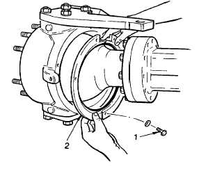
(1)
Remove ball seal retainer capscrews (1)
and lockwashers; then carefully pry retainer
(2) and seal from its mounting.
2-280
|