|
| |
TM 9-254
8-6.
Waveform Reading - Continued
(4)
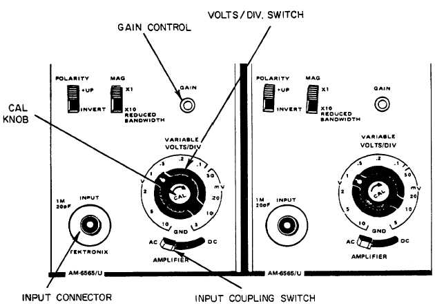
Place input coupling AC/GND/DC switch, on the left vertical amplifier, to the AC position (fig. 8-12).
Figure 8-12. VOLTS/DIV Control
(5)
Set the VOLT/DIV switch (2, fig. 8-9) to the .5 volt position. This means that each vertical square is
equal to .5 volts of input signal.
(6)
Turn the CAL KNOB (3, fig. 8-9) fully clockwise until it clicks.
(7)
Obtain a cable with a BNC connector on each end and connect one end to the CALIBRATOR (9, fig. 8-
8) and the other end to the INPUT connector of the left vertical amplifier (fig. 8-12).
(8)
You should have two complete cycles of square wave displayed on the screen as shown in figure 8-13. It
may be necessary to adjust the LEVEL control, (15, fig. 8-10) to obtain a stable display. Adjust both
POSITION knobs (8, fig. 8-9) and (13, fig. 8-10) to center the displayed waveform.
8-18
|