|
| |
TM 9-254
4-17. Printed Circuit Board - Continued
(4)
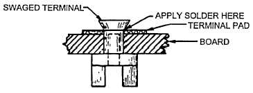
Make a V or funnel type swage on the terminal. The point of the V swage should enter the terminal shank only far
enough to produce a hand tight fit of the terminal as shown in figure 4-43. If solder rings are used, place the ring
over the terminal shank before swaying. Solder rings are recommended since they give a more uniform and
reliable solder joint.
Figure 4-43. Terminal After Swaging
(4)
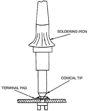
Place the soldering iron tip over the terminal head, as shown in figure 4-44, and apply solder to the joint where the
terminal shank and pad intersect. Allow the solder to flow properly and then remove the soldering iron tip from
the terminal head. The solder should completely cover the pad and form a neat uniform joint.
Figure 4-44. Soldering Swaged Terminal
(4)
Carefully clean the soldered joint with alcohol and a medium stiff bristle brush.
(5)
Inspect all joints. If any joint should require resoldering, add a small amount of new solder after reheating the
joint.
4-45
|