 |
|||
|
|
|||
|
|
|||
| ||||||||||
|
|
 TM 9-1240-375-34&P
0104 00
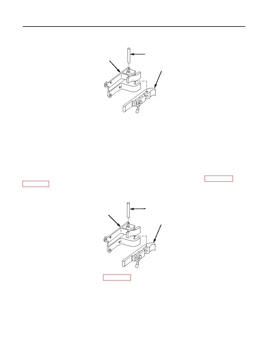
DISASSEMBLY
1
3
2
1fc742
1.
Remove headless straight pin (1).
2.
Remove optical instrument latch (2) from latch holder (3).
REPAIR OR REPLACEMENT
NOTE
Replace entire optical instrument latch set if damaged to the extent that the
M138/M138A1 telescope does not lock securely in position.
Repair is by replacement of authorized parts that do not meet inspection criteria. Refer to WP 0145 00 and
ASSEMBLY
3
2
1
1fc743
1.
Apply light coat of grease (item 15, WP 0152 00) to optical instrument latch (1) and position in latch
holder (2).
NOTE
Ensure headless straight pin is below surface of latch holder on both sides.
2.
Install headless straight pin (3).
0104 00-2
|
|
Privacy Statement - Press Release - Copyright Information. - Contact Us |
