 |
|||
|
|
|||
|
|
|||
| ||||||||||
|
|
 TM 9-1240-375-34&P
0099 00
10.
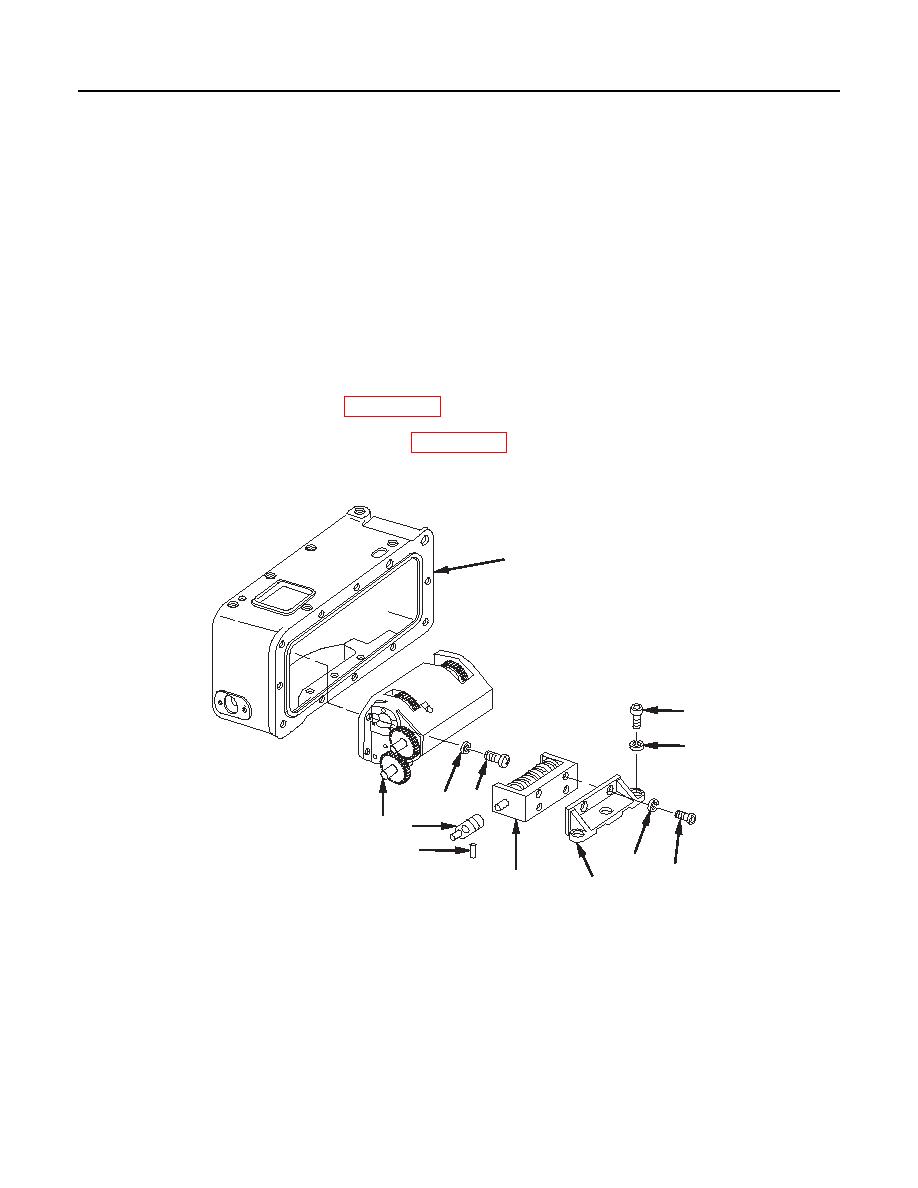
Set reset coupling (9) so that setscrew is accessible and tighten.
11.
Turn knob to be sure that rotating counter numbers are in correct alignment. If not, loosen setscrew
and realign rotating counter (6) until numbers are aligned as seen through optical instrument window.
Tighten setscrew.
12.
Remove rotating counter (6) with counter mount (5) from counter box assembly (2).
13.
Drill pin hole in reset coupling (9) and shaft of rotating counter (6). Install headless straight pin (10).
14.
Remove setscrew from reset coupling (9).
15.
If using original parts, install reset coupling (9) and secure with headless straight pin (10).
16.
Set rotating counter (6) to 00 and install.
17.
Apply sealing compound (item 13, WP 0152 00) to threads of three socket head capscrews (11).
18.
Install three new lockwashers (12) (item 4, WP 0142 00) and three socket head capscrews (11) to secure
counter mount (5) to counter box assembly (2).
2
11
12
3
4
1
9
10
8
7
6
5
1 fc 6 2 8
0099 00-5
|
|
Privacy Statement - Press Release - Copyright Information. - Contact Us |