 |
|||
|
|
|||
|
|
|||
| ||||||||||
|
|
 TM 9-1240-375-34&P
0050 00
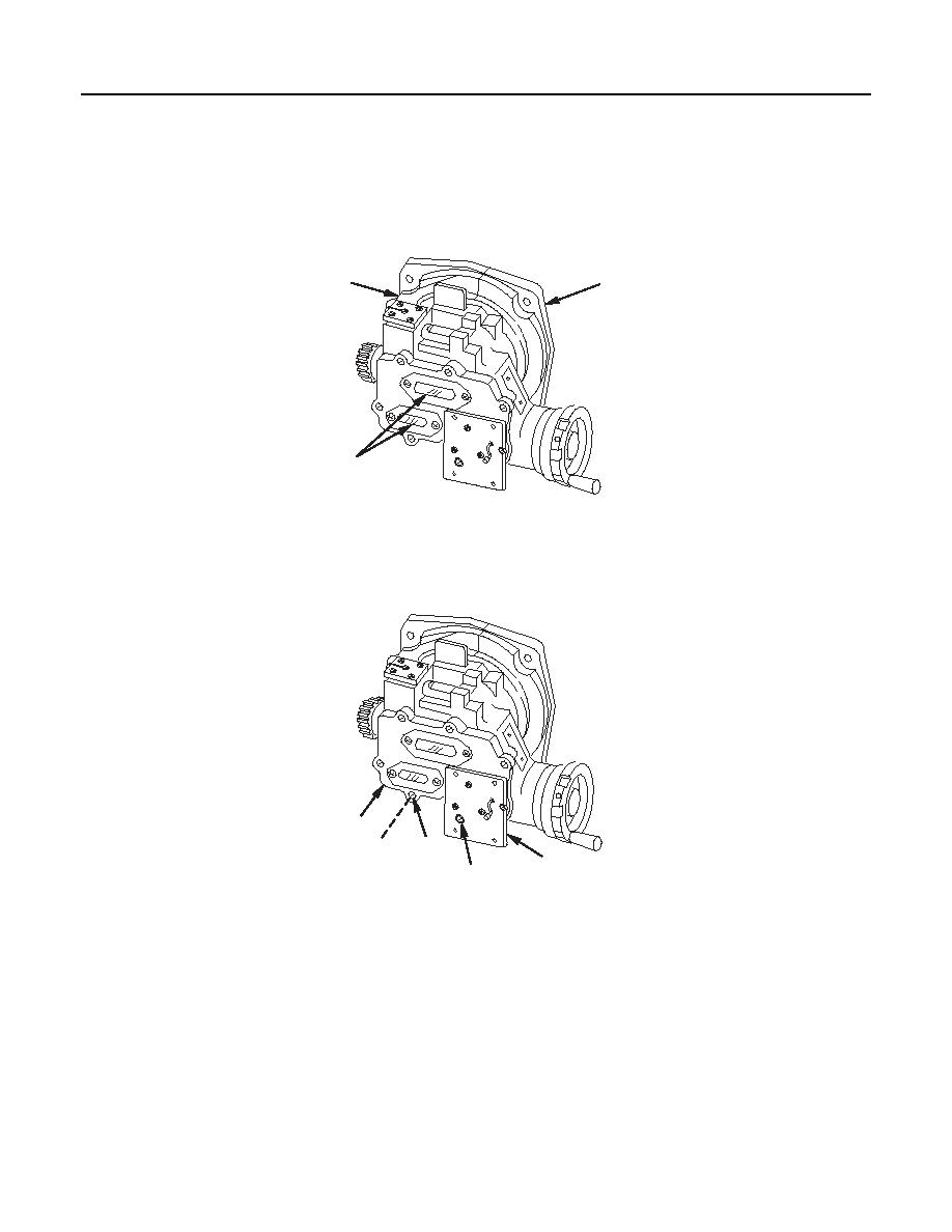
DISASSEMBLY
NOTE
The following steps are written and illustrated for the M17A1 quadrant but also
apply to the M18A1 quadrant.
2
3
1
1 fc 1 2 6
M17A1/M18A1 Quadrant
1.
Set counters (1) at zero. Scribe a line on base assembly (2) and housing assembly (3) to facilitate
correct counter installation.
5
6
7
4
8
1 fc 1 2 7
M17A1/M18A1 Quadrant
CAUTION
Do not attempt to remove adapter plate (4) from cover assembly (5). A short wire
harness passing through adapter plate cannot be removed without damaging
equipment. Adapter plate can only be removed or installed by the manufacturer.
Two access holes are provided in adapter plate to allow cover assembly removal.
2.
Remove seven machine screws (6) and seven lockwashers (7) from cover assembly (5). Discard
3.
Remove plug (8) from adapter plate (4).
0050 00-2
|
|
Privacy Statement - Press Release - Copyright Information. - Contact Us |
