 |
|||
|
|
|||
|
|
|||
| ||||||||||
|
|
 TM 9-1240-375-34&P
0047 00
ASSEMBLY - Continued
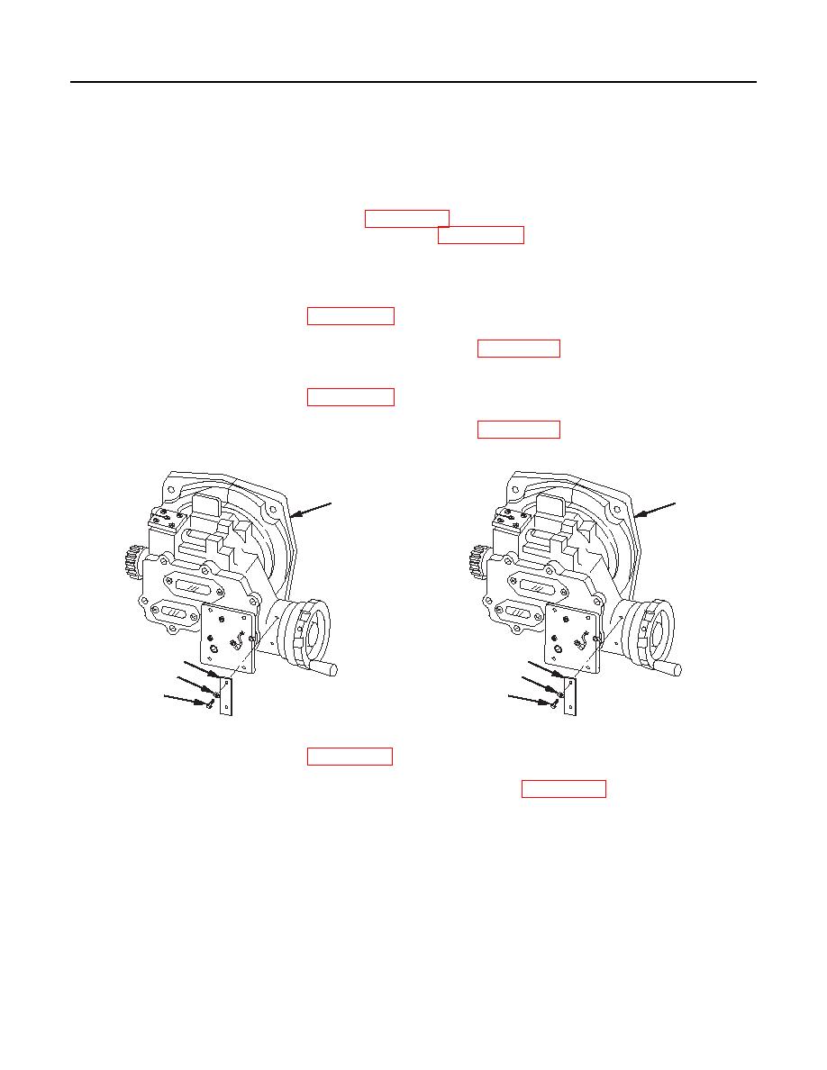
8.
If removed, install new cushioning pad (10) and new setscrew (11) to fire control level assembly (12).
Do not tighten setscrew.
9.
Install adjusting plate (9) on fire control level assembly (12).
10.
Install four new lockwashers (13) (item 4, WP 0111 00) and four machine screws (14). Tighten machine
screws and fill heads with sealing compound (item 13, WP 0152 00).
11.
Start screw (15) into adjusting plate (9) but do not tighten. Screw will be tightened and locked with
setscrew (11) during adjustment.
12.
Apply sealing compound (item 13, WP 0152 00) to threads of two machine screws (16).
13.
Install reflector (17) with two new lockwashers (18) (item 4, WP 0111 00) and two machine screws (16).
Tighten machine screws.
14.
Apply sealing compound (item 13, WP 0152 00) to threads of two machine screws (19).
15.
Install reflector (20) with two new lockwashers (21) (item 9, WP 0111 00) and two machine screws (19).
Tighten machine screws (M18A1 only).
25
25
23
23
24
24
22
22
1 fc 0 8 7
1 fc 0 8 8
M17A1 Quadrant
M18A1 Quadrant
16.
Apply sealing compound (item 13, WP 0152 00) to threads of two machine screws (22).
17.
Install identification plate (23), two new lockwashers (24) (item 13, WP 0111 00), and two machine
screws (22) on side of quadrant (25).
0047 00-8
|
|
Privacy Statement - Press Release - Copyright Information. - Contact Us |
