 |
|||
|
|
|||
|
|
|||
| ||||||||||
|
|
 TM 9-1240-375-34&P
0002 00
LOCATION AND DESCRIPTION OF MAJOR COMPONENTS - Continued
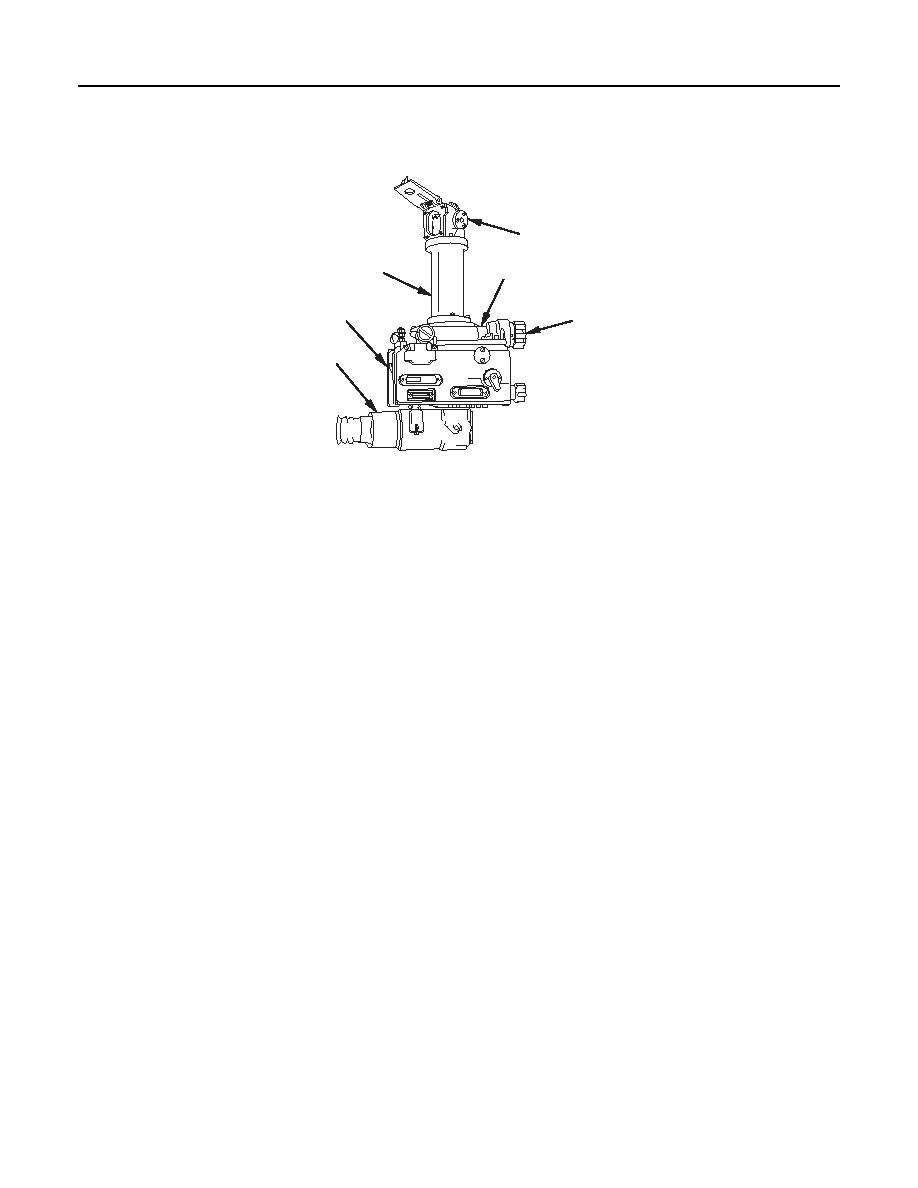
M137 Panoramic Telescope
1
2
3
6
4
5
M 137
1 fc 0 1 3
1.
Head Assembly (1). The head assembly is capable of 360-degree (6400 mil) revolution. The amount of
azimuth travel is indicated by a counter box assembly. The head assembly is adjustable in elevation
( 300 mils) by means of an elevation knob. An entrance window protects the prism and the rest of the
M137 telescope against moisture, dirt, and other foreign particles. A window cover, when in the closed
position, forms a parallax shield to reduce parallax when viewing a close target.
2.
Optical Element Spacer (2). The optical element spacer couples the head assembly to the body
assembly at a sufficient height so the line of sight has minimum obstructions.
3.
Body Assembly (3). The body assembly includes the main M137 telescope tube and housing and the
radioactive sources that illuminate the reticles. This assembly also includes the azimuth knob
assembly and associated gearing that rotates the head assembly and drives the counter box assembly.
One rotation of the azimuth knob assembly rotates the head assembly 100 mils.
4.
Knob Assembly (4). The knob assembly is located on the body assembly. It is used to activate the
worm shaft assembly which rotates the head assembly.
5.
Elbow Assembly (5). The elbow assembly is located on the bottom of the M137 telescope. The elbow
assembly contains the optical cell assembly and adapter assembly.
6.
Counter Box Assembly (6). The counter box assembly contains the 6400-mil azimuth counter, the
6400-mil deflection counter, and the 95-mil correction counter. It also contains the associated gearing
for driving and setting the counters.
a.
The azimuth counter indicates the azimuth angle of the M137 telescope head assembly with
respect to the weapon bore.
b.
The deflection counter indicates the azimuth angle in mils. It enables an operator to quickly lay
the weapon on a desired deflection setting with respect to the aiming posts or collimator.
c.
The correction counter indicates relatively constant deflection correction.
0002 00-10
|
|
Privacy Statement - Press Release - Copyright Information. - Contact Us |
