 |
|||
|
|
|||
|
Page Title:
M18A1 Fire Control Quadrant |
|
||
| ||||||||||
|
|
 TM 9-1240-375-34&P
0002 00
LOCATION AND DESCRIPTION OF MAJOR COMPONENTS - Continued
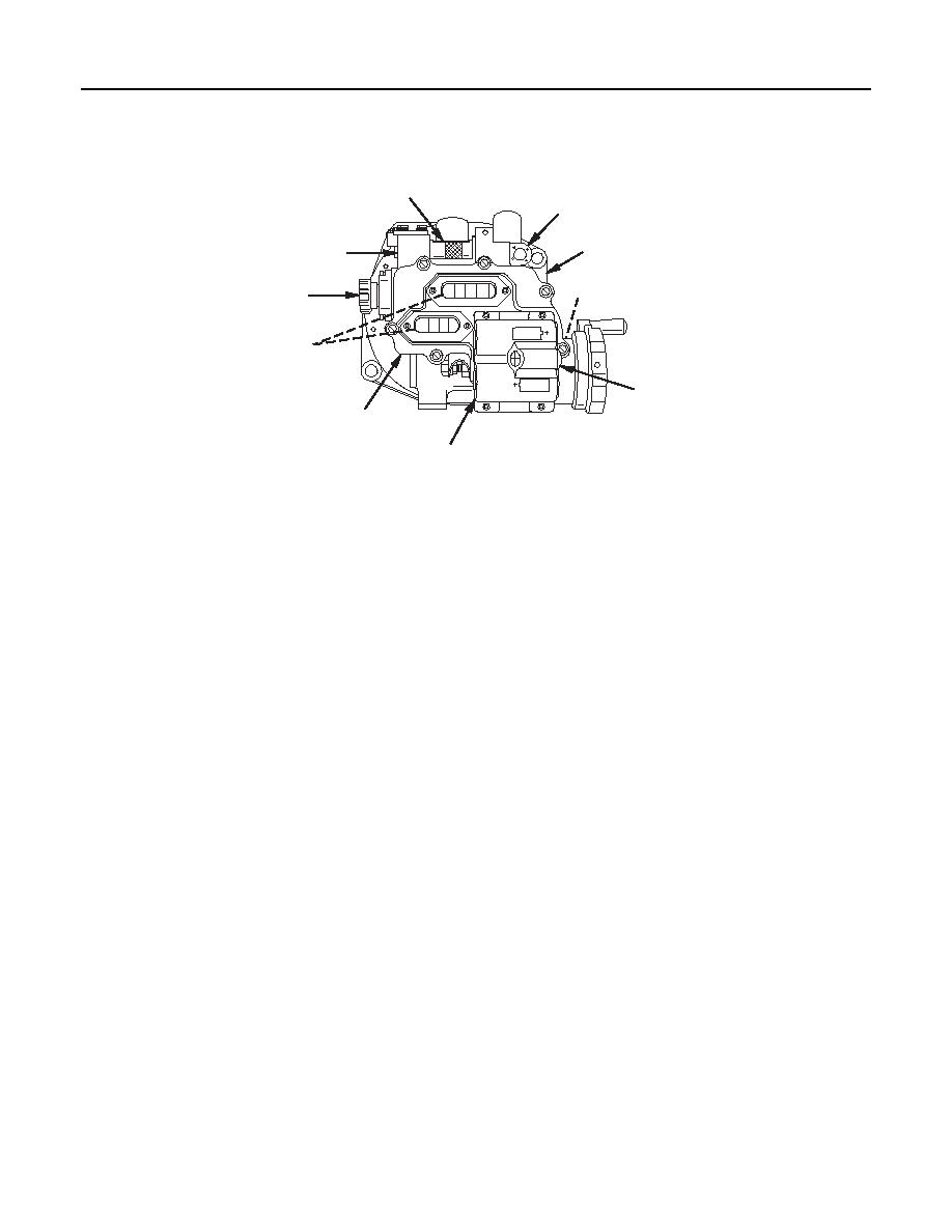
M18A1 Fire Control Quadrant
1
2
6
8
7
4
5
10
3
9
M 18A1
1 fc 0 0 9
1.
Fire Control Elevation Level Assembly (1). The fire control level assembly consists of an elevation level
vial in a vial holder. The fire control level assembly is used in checking the cannon in elevation.
2.
Cross Level Assembly (2). The cross level assembly is located on the upper right side of the M18A1
quadrant. The level assembly consists of a cross level vial in a vial holder, and is used in checking the
howitzer for cross level.
3.
Cover Assembly (3). The cover assembly of the M18A1 quadrant includes the counter windows, the
LED light sources that illuminate the dials, and the battery enclosure assembly with power switch.
4.
Correction Knob Assembly (4). The correction knob assembly is located on the left side of the M18A1
quadrant. It is used to set elevation correction increments on the correction counter.
5.
Counter Assembly (5). The counter assembly consists of the elevation counter and the correction
counter. The counters are mounted in the housing assembly.
6.
Base Assembly (6). The base assembly provides the mounting surface for the M18A1 quadrant. It also
contains a bearing necessary for accurate rotation when setting elevation.
7.
Worm Shaft Assembly (7). The worm shaft assembly is located internally and is controlled by the
elevation knob. The worm shaft assembly is used to level the M18A1 quadrant in elevation by moving
the elevation and correction counters.
8.
Housing Assembly (8). The housing assembly for the M18A1 quadrant contains an elevation knob
assembly, correction knob assembly, counter assembly, level assembly, fire control level assembly, and
a worm shaft assembly.
9.
Battery Enclosure Assembly (9). The battery enclosure is located on the left front side of the M18A1
cover. It is used to hold the batteries and is equipped with a power switch.
10.
Battery Power Switch (10). The power switch is located on the left front side of the battery enclosure
assembly. It is used to cycle the battery power on and off. The power switch has a three-second delay.
0002 00-6
|
|
Privacy Statement - Press Release - Copyright Information. - Contact Us |
