 |
|||
|
|
|||
|
|
|||
| ||||||||||
|
|
 TM 55-1925-292-14&P
0026 00
INSTALLATION
1. Position time delay module TL-30U (figure 4, item 4) in the enclosure and secure it with the four screws
(figure 4, item 3).
2. Connect the electrical wiring to P1 (figure 4, item 1) and P2 (figure 4, item 2) using the labels from step 2 of
Removal as a guide. Remove the labels.
3. Perform the Follow-On Service procedure at the end of this work package.
METER MODULE MM-35 REPLACEMENT
REMOVAL
1. OPEN the enclosure following the Open Enclosure procedure at the of this work package.
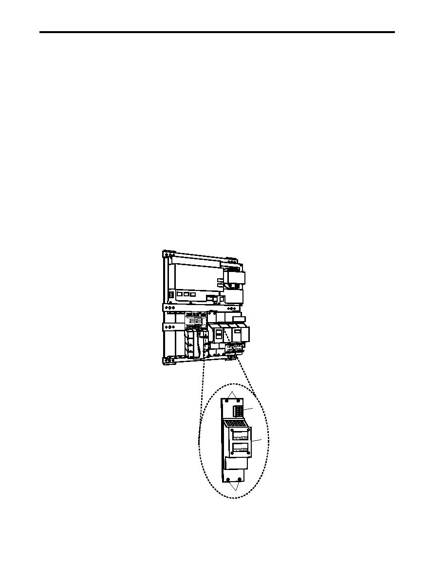
2. Label and disconnect the electrical wiring from P1 (figure 5, item 1).
3. Remove the four screws (figure 5, item 2) that secure meter module MM-35 (figure 5, item 3), and remove it
from the enclosure.
CP-35
PS 35
BC-35
MM-35
BE-35
2
MM-35
1
DCVOLTS
3
DCAMPS
2
Figure 5. Meter Module MM-35 Replacement
0026 00-6
|
|
Privacy Statement - Press Release - Copyright Information. - Contact Us |
