 |
|||
|
|
|||
|
Page Title:
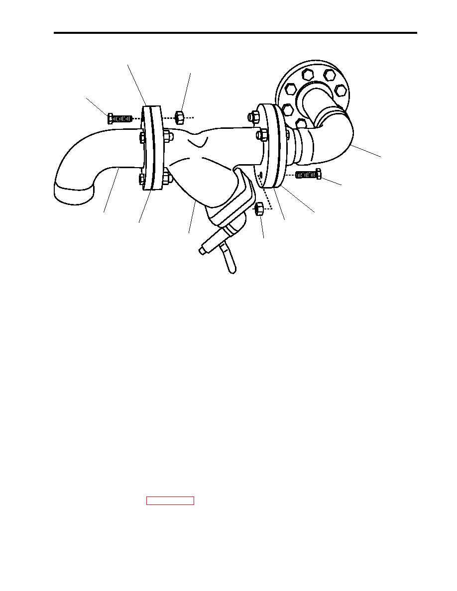
Figure 3. AFFF Pump Inlet Strainer-Replacement |
|
||
| ||||||||||
|
|
 TM 55-1925-292-14&P
0020 00
3
2
1
6
1
3
6
4
4
5
2
Figure 3. AFFF Pump Inlet Strainer-Replacement
INSTALLATION
1. Position the new strainer assembly (figure 3, item 5) to the piping (figure 3, item 6) with the new gaskets
(figure 3, item 4), and loosely secure with the four bolts (figure 3, item 1) and four nuts (figure 3, item 2) for
each flange (figure 3, item 3). Loosen the clamp on the section line as needed.
2. Ensure that the flanges (figure 3, item 3) are aligned before tightening the bolts (figure 3, item 1).
3. Tighten the four bolts (figure 3, item 1) on each flange (figure 3, item 3).
4. Perform the Follow-On Service procedure at the end of this work package.
FOLLOW-ON SERVICE
1. Remove the lockouts and tagouts (FM 55-502).
2. Set to ON the AFFF PUMP circuit breaker on the main switchboard.
3. OPEN valve FM-84, AFFF TK SUCT.
4. Operate the AFFF pump (WP 0005 00) and observe that the system operates normally without leakage or
unusual noises.
5. Return the equipment to the desired readiness condition.
END OF WORK PACKAGE
0020 020506 -5lank
0 0- / 0 b
|
|
Privacy Statement - Press Release - Copyright Information. - Contact Us |
