 |
|||
|
|
|||
|
|
|||
| ||||||||||
|
|
 TM 55-1925-292-14&P
0016 00
6. Remove and discard the valve body seal (figure 6, item 9) from the valve body (figure 6, item 3).
7. Remove the seat (figure 6, item 10), the ball (figure 6, item 11), and the remaining seat (figure 6, item 12)
from the valve body (figure 6, item 3).
8. Inspect all component parts for unusual wear or damage.
9. Inspect for any binding, scoring, or burrs on the valve stem bearing (figure 6, items 7).
ASSEMBLY
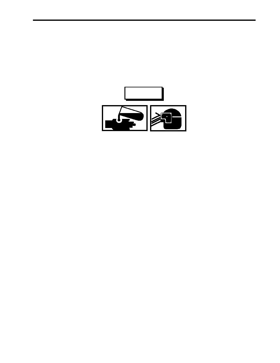
WARNING
Do not allow cleaning solvents to come in contact with unprotected skin or eyes.
Prolonged skin contact can cause illness or injury. Eye contact can cause seri-
ous injury. Always wear chemical protective gloves and goggles when handling
hydraulic fluid, engine oil, and cleaning solvents. Failure to follow these precau-
tions can result in illness or serious injury.
Removing components by means of wire brushing produces flying particles. These
particles can cause serious injury to personnel. Protective goggles, gloves, and
long sleeves must be worn at all times during wire brushing operations. Failure
to comply with this warning can result in serious injury to personnel.
1. Using a wire brush and dry cleaning solvent, clean all metal parts of the valve.
2. Install the seat (figure 6, item 12), the ball (figure 6, item 11), and the remaining seat (figure 6, item 10) in the
valve body (figure 6, item 3).
3. Install a new valve body seal (figure 6, item 9) on the retainer (figure 6, item 8).
4. Install the retainer (figure 6, item 8) in the valve body (figure 6, item 3).
5. Install the valve stem bearing (figure 6, item 7) and the valve stem (figure 6, item 6) in the valve body
(figure 6, item 3).
6. Install the new stem packing (figure 6, item 5) in the valve body (figure 6, item 3).
7. Install the packing gland (figure 6, item 4) in the valve body (figure 6, item 3). Tighten the packing gland.
8. Install the handle (figure 6, item 2) with the the lever nut (figure 6, item 1) on the valve body (figure 6, item 3).
Tighten the lever nut.
9. Perform the Typical Ball Valve Installation procedure in this work package.
10. Perform the Follow-On Service procedure at the end of this work package.
0016 00-11
|
|
Privacy Statement - Press Release - Copyright Information. - Contact Us |