 |
|||
|
|
|||
|
|
|||
| ||||||||||
|
|
 TM 55-1925-292-14&P
0016 00
6. Remove the four bolts (figure 4, item 3) and the four nuts (figure 4, item 4), and remove the valve (figure 4,
item 2) from the standing piping.
7. Remove and discard the gasket (figure 4, item 5).
INSTALLATION
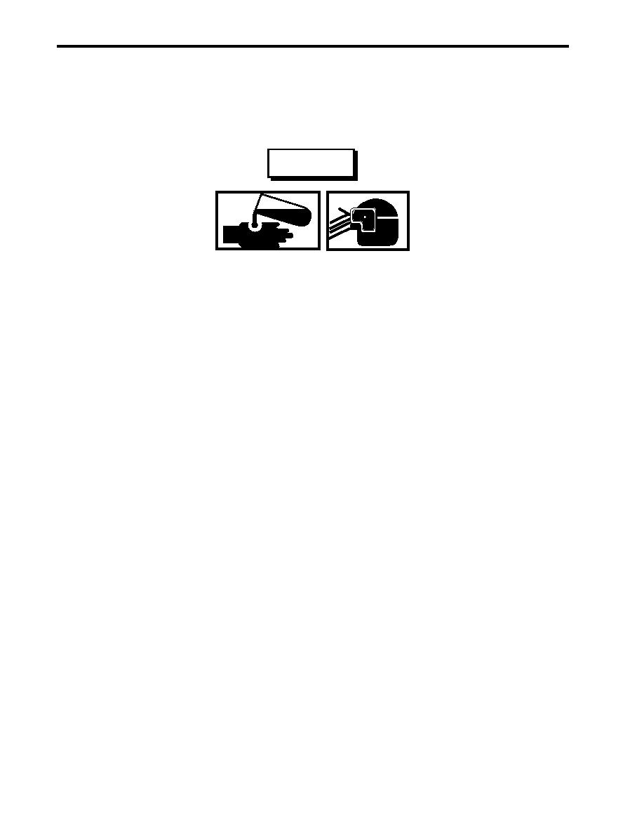
WARNING
Do not allow cleaning solvents to come in contact with unprotected skin or eyes.
Prolonged skin contact can cause illness or injury. Eye contact can cause seri-
ous injury. Always wear chemical protective gloves and goggles when handling
hydraulic fluid, engine oil, and cleaning solvents. Failure to follow these precau-
tions can result in illness or serious injury.
Removing components by means of wire brushing produces flying particles. These
particles can cause serious injury to personnel. Protective goggles, gloves, and
long sleeves must be worn at all times during wire brushing operations. Failure
to comply with this warning can result in serious injury to personnel.
1. Using a wire brush and dry cleaning solvent, clean the piping flange (figure 4, item 7).
2. Install a new gasket (figure 4, item 5) on the piping flange (figure 4, item 7). Place the valve (figure 4, item 2)
on the piping flange.
3. Secure the valve (figure 4, item 2) with the four bolts (figure 4, item 3) and the four nuts (figure 4, item 4).
4. Perform the Follow-On Service procedure at the end of this work package.
TYPICAL FLANGED GLOBE STOP CHECK VALVE REPLACEMENT
REMOVAL
1. Partially OPEN the valve (figure 5, item 1) to vent any pressure.
2. Place a suitable drain pan under the valve (figure 5, item 1).
3. Loosen, but do not remove, the eight bolts (figure 5, item 2) and the eight nuts (figure 5, item 3) and allow any
fluid to drain into the suitable drain pan.
4. After the fluid drains from the valve (figure 5, item 1), remove the eight bolts (figure 5, item 2) and the eight
nuts (figure 5, item 3).
6. Remove and discard the gaskets (figure 5, item 4), and remove the valve (figure 5, item 1) from the vessel
piping.
0016 00-8
|
|
Privacy Statement - Press Release - Copyright Information. - Contact Us |