 |
|||
|
|
|||
|
|
|||
| ||||||||||
|
|
 TM 55-1925-292-14&P
0006 00
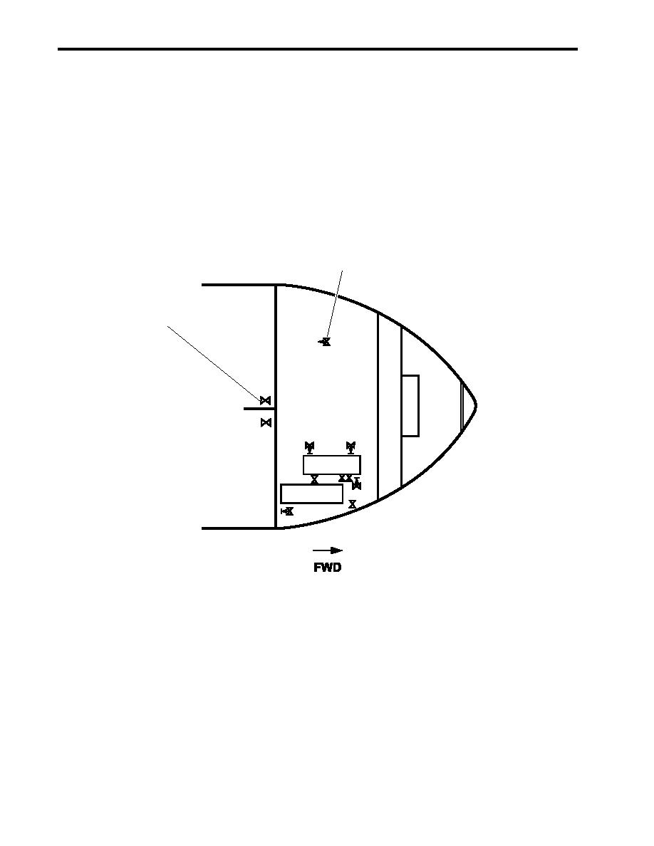
2. OPEN valve FM-1, SEA SUCT, F.F. PMP (figure 2, item 1), located beneath the EOS.
3. Start the pump drive engine (TM 55-1925-273-10).
4. Prime the diesel engine-driven firefighting pump by placing the following valves in the OPEN position:
a. GS-111, FF PMP PRM EDUCTOR DISCH (figure 3, item 1)
b. CA-73, SVCE AIR TO FF PMP PRM EDUCTOR (figure 3, item 2)
5. When water discharges from the overflow line (figure 3, item 3), CLOSE the following valves:
a. CA-73, SVCE AIR TO FF PMP PRM EDUCTOR (figure 3, item 2)
b. GS-111, FF PMP PRM EDUCTOR DISCH (figure 3, item 1)
2
Engine Room
AMS 1
1
FM-13
FM-1
(BELOW
EOS) ASW-17
ASW-19
ASW-20
PUMP DRIVE
ENGINE
FO-31
HYDRAULIC CA-6
SUPPLY TANK
ASW-22
FM-84
STBD
Figure 2. Valve Locations
6. Engage the Power Take-Off (PTO) (TM 55-1925-273-10).
7. OPEN FM-13, F.F. TO F.M. CRSVR (figure 2, item 2), fire pump to fire main cross connect, located in the
overhead in AMS 1.
8. To return the fire and general service pump(s) to normal service, perform the following steps:
a. Secure the pump drive engine (TM 55-1925-273-10).
b. CLOSE FM-13, F.F. TO F.M. CRSVR (figure 2, item 2).
c.
OPEN FM-14, FIRE/G.S. NO.2 DISCH TO FM (figure 1, item 2) or FM-16, FIRE/G.S. NO.1 DISCH TO
FM (figure 1, item 1) as required for the online fire and general service pump.
0006 00-2
|
|
Privacy Statement - Press Release - Copyright Information. - Contact Us |
