 |
|||
|
|
|||
|
Page Title:
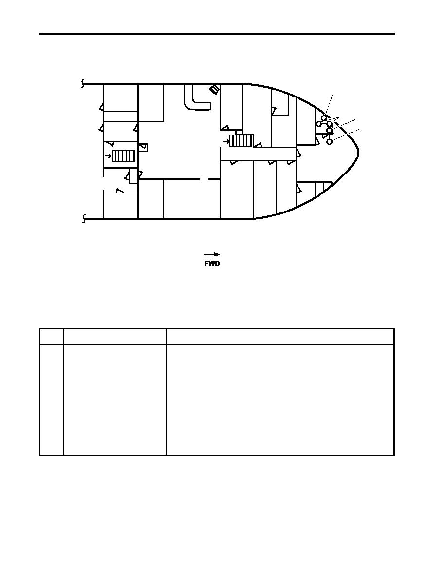
Figure 11. Arms Locker Drenching System |
|
||
| ||||||||||
|
|
 TM 55-1925-292-14&P
0004 00
ARMS LOCKER DRENCHING SYSTEM
1
2
3
T
W
W
4
P
D.C.
UP
LOCKER
M
CREW'S MESS/
BOATSWAIN'S
DN
RECREATION AREA
STORES
GALLEY
MAIN DECK
Figure 11. Arms Locker Drenching System
Table 11. Arms Locker Drenching System (refer to figure 11)
Key
Control/Indicator
Function
1
Thermal Heat Detectors
These detectors sense temperatures in excess of 135 F (55.2 C).
2
Arms Locker Drenching
These heads, when manually activated, release raw water to cool
System Sprinkler Heads
or extinguish fires in the arms locker.
3
Pressure Switch
This switch alarms the pilothouse when the drenching system is
activated.
4
Manually Activated Valve
This valve activates the arms locker drenching system. It can be
activated from the arms locker (local) or the 0-1 level (remote)
at the bow by way of a reach rod valve system.
END OF WORK PACKAGE
0004 00-14
|
|
Privacy Statement - Press Release - Copyright Information. - Contact Us |
