 |
|||
|
|
|||
|
Page Title:
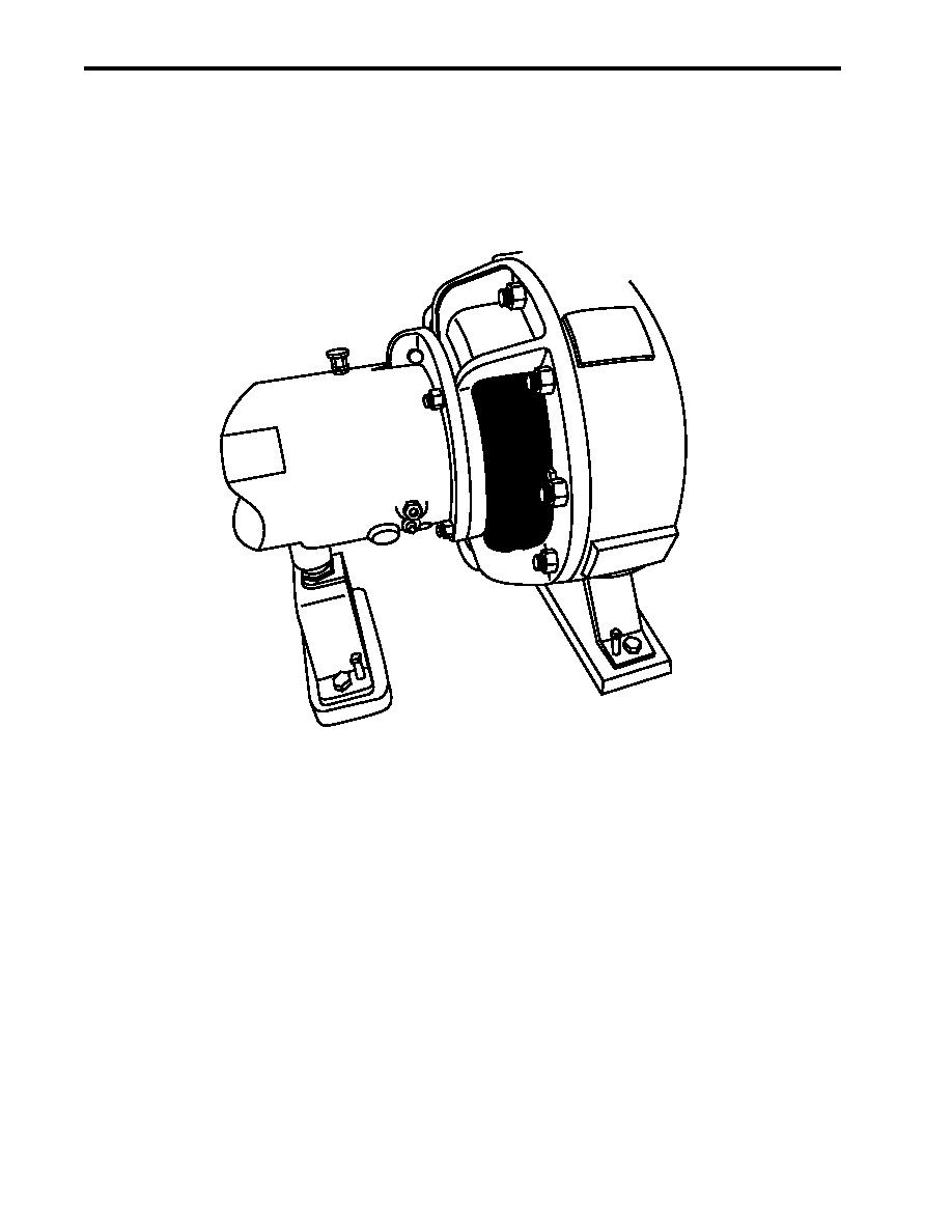
Figure 18. Diesel Engine-Driven Firefighting Pump |
|
||
| ||||||||||
|
|
 0003 00
TM 55-1925-292-14&P
DIESEL ENGINE-DRIVEN FIREFIGHTING PUMP
The diesel engine-driven firefighting pump (figure 18) is located in AMS 1. Its rated capacity is 1000 gal/min
(3785 L/min) with a discharge pressure of 125 PSI (8.6 bar). Its primary purpose is to provide raw water to the
fire monitors. The secondary purpose of the pump is to pressurize the fire main and general service system in
the event of a malfunction of the fire and general service pumps.
Figure 18. Diesel Engine-Driven Firefighting Pump
GALLEY FIRE SUPPRESSION SYSTEM
The galley fire suppression system is designed to extinguish fires that originate in the galley and the galley
cooking equipment. The galley fire suppression system is a pre-engineered, wet chemical, cartridge operated,
regulated pressure type extinguishing system. The system is capable of manual activation through the use of a
fire alarm pull station (figure 19, item 1) or automatic actuation through the use of fusible links (figure 19, items
2 and 3) rated at 500 F (260 C) and 360 F (182 C), respectively.
The extinguishing agent is formulated with an aqueous solution of organic salts with a ph range between 7.8 and
8.2. It is designed for flame knock down and foam coverage of grease related fires. The wet chemical agent is
stored in a 3-gallon (11.3 liter) carbon steel tank housed in a stainless steel enclosure (figure 19, item 4) mounted
on the starboard bulkhead of the galley. The storage tank has a working pressure of 100 PSI (6.9 bar). The
extinguishing agent is propelled by the use of a gas cartridge of carbon dioxide or nitrogen gas and delivered to
the distribution nozzles (figure 19, item 5). The distribution nozzle tips have blow off caps to keep the nozzle
orifices free of cooking grease buildup.
0003 00-20
|
|
Privacy Statement - Press Release - Copyright Information. - Contact Us |
