 |
|||
|
|
|||
|
Page Title:
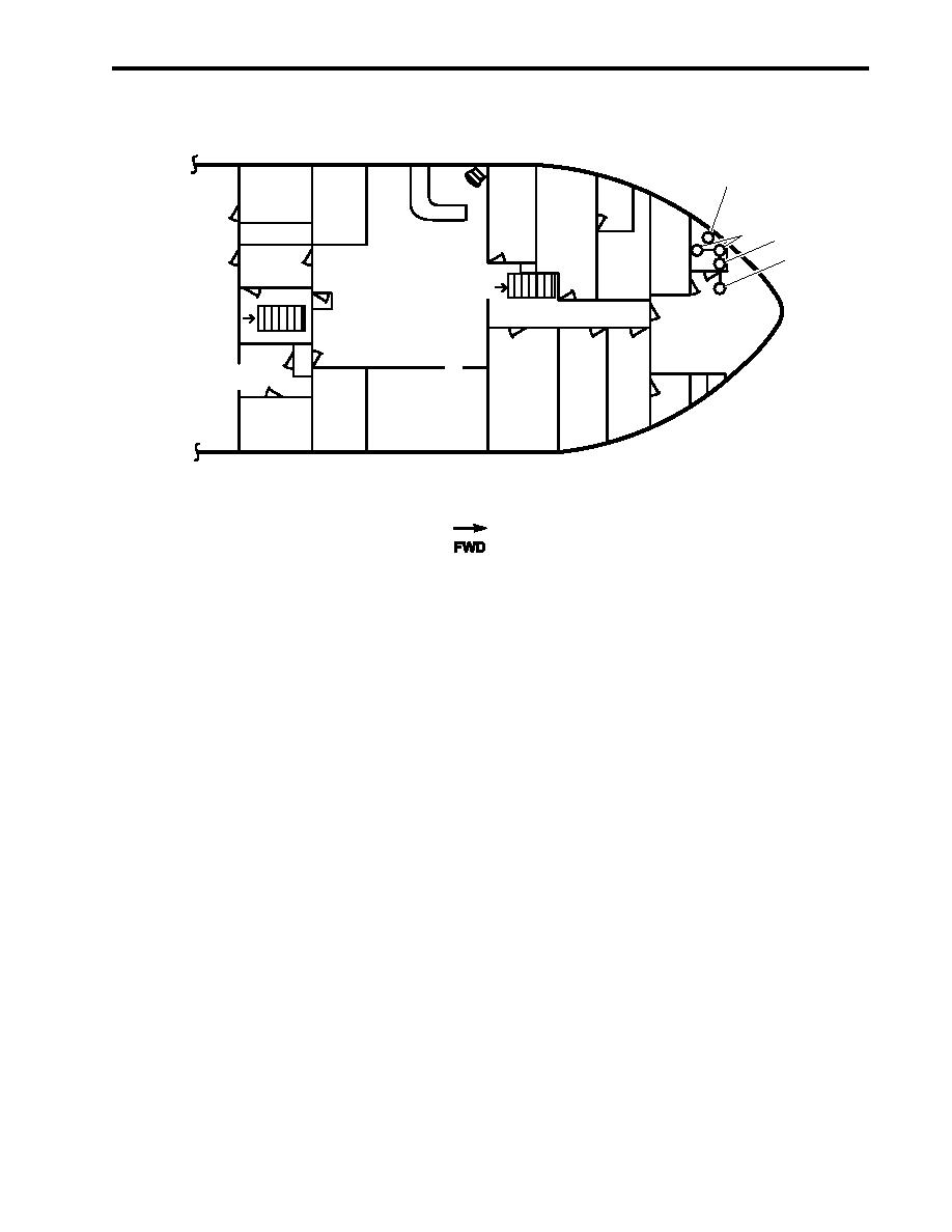
Figure 10. Arms Locker Drenching System |
|
||
| ||||||||||
|
|
 TM 55-1925-292-14&P
0002 00
ARMS LOCKER DRENCHING SYSTEM
1
2
3
T
W
W
4
P
D.C.
UP
LOCKER
M
CREW'S MESS/
BOATSWAIN'S
DN
RECREATION AREA
STORES
GALLEY
MAIN DECK
Figure 10. Arms Locker Drenching System
LOCATION AND DESCRIPTION OF MAJOR COMPONENTS
1. Thermal Seat Detector (figure 10, item 1). This detector is activated at 105 F and sounds an alarm in the
pilothouse.
2. Sprinkler Heads (figure 10, item 2). These two sprinkler heads provide raw water to the arms locker after the
manual activation valve has been OPENED.
3. Pressure Switch (figure 10, item 3). This switch sends an alarm to the pilothouse once the sprinkler heads
have been activated.
4. Manual Activation Valve (figure 10, item 4). This valve controls the supply of raw water to the arms locker.
The valve can be operated from the boatswain's locker (local) or from the 01 level (remote) by the use of a
reach rod valve system.
0002 00-21
|
|
Privacy Statement - Press Release - Copyright Information. - Contact Us |
