|
| |
TM 5-4210-233-14&P-1
5-43. FORWARD TANDEM AXLE AND DRIVE UNIT-Continued
(70)
Use a press to install yoke (11) on shaft. Install nut (10) on output shaft (16) and torque to 450 to
650 lb ft (610 to 881 N•m).
(71)
Apply silicone sealant adhesive (Item 35, Appendix E) material to mounting surface of axle housing
(83) where differential assembly mounts.
(72)
Using a hoist lift the assembled differential carrier assembly (5) into position on axle housing (83).
Install four washers (8), one nut (7) and three screws (6) in four corner locations around the carrier.
Tighten screws and nut by hand. Do not tighten to specified torque.
(73)
Carefully push the differential carrier into position. Tighten the four fasteners two or three turns
each in a pattern opposite each other. Continue tightening until the final step. Torque nut (7) and
screws (6) to a torque of 150 to 230 lb ft (203 to 212 N•m).
(74)
Install other two nut (7), seven washers (8) and five screws (6) and tighten to specified torque.
(75)
Install axle shafts (84 and 85) in axles.
(76)
Install plugs (1, 84 and 85) and breathers (86) in housing.
(77)
Adjust the fork on the differential shift assembly.
(a) Loosen the jam nut (49). Loosen the adjusting screw (48) until adjusting screw (48) does not
touch shift shaft (45).
NOTE
Make sure the adjusting screw (48) does not touch the shift shaft
(45) when the shift collar (37) engages the differential case
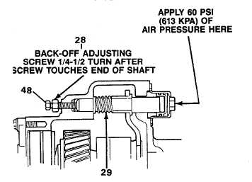
(40).APPLY 60 PSI
(b) Connect an air supply to shift assembly (44).
Apply and hold 60 psi (613 kPa) of air
pressure to shift assembly so that shift collar
(37) engages splines of differential case (40).
(c) Tighten adjusting screw (48) until tip of screw
touches end of shift shaft (28). When top
touches shaft, tighten adjusting screw an
additional one-quarter to one-half turn.
(d) Release the air pressure. Check to see that
the differential (40) is disengaged by holding
the input yoke (23) and rotative output yoke
(11). The output yoke (11) must rotate freely.
(e) Apply and hold 60 psi (613 kPa) of air pressure to shift assembly to make sure the shift collar (37)
engages the splines of the deferential case.
(f)
With air pressure applied, when the input yoke is rotated the output yoke must rotate. Torque
jam nut (49) to 40 to 55 lb ft (55 to 75 N•m).
(g) Disconnect air pressure and hose from shift assembly.
5-320
|