|
| |
TM 5-4210-233-14&P-1
5-43. FORWARD TANDEM AXLE AND DRIVE UNIT-Continued
(61)
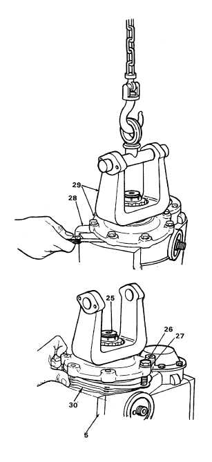
Check and adjust end play of input
bearings (33 and 50). Place a wood
block between ring gear (19) and case
to keep ring gear (19) from turning.
(a) Install seven screws (26) but not
washers (27) to fasten input bearing
cage to carrier. Rotate input shaft (25)
in each direction to make sure bearings
are correctly installed while tightening
screws (27) by hand.
(b) Use a feeler gauge to measure gap
between bearing cage (28) and
differential carrier housing (5). Check
gap at four equidistant places on cage.
(c) Add up the four measurements and
divide by four to arrive at the average
gap. Add 0.005 inch (0.13 mm) to the
average to determine size of shim
pack (30).
(d) Use at least three shims (30) to build a
shim pack (30). Install the thickest
shims in the middle of the shim pack.
(e) Remove the seven screws (26) used to
temporarily fasten bearing cage (28) to
differential carrier housing (5). Connect
a lifting device to input yoke. Lift input
shaft assembly (29) until there is a
distance of 0.25 to 0.50 inch (6 to 12
mm) between cage (25) and differential
carrier (51) mounting surface.
(f)
Install shim pack (30) under bearing
cage (25). Make sure installation
pattern of shim pack matches
installation pattern of cage.
(g) Lower the input shaft assembly (29)
into position over differential carrier
housing (5). Remove lifting device.
Install washers (27) and screws (26)
and torque screws to 75 to 95 lb ft (100
to 130 N•m) while rotating the input
shaft (25) in each direction to make
sure the input bearings (33 and 50) are
correctly installed.
5-317
|