|
| |
TM 5-4210-233-14&P-1
5-40. FRONT STEERING AXLE-Continued
(10)
Remove four lubrication fittings (24)
from caps (27).
(11)
Remove twelve screws (25) and
washers (26) and remove caps (27).
Remove and discard gaskets (28).
(12)
Loosen lock nuts (29). Use a brass drift
and hammer to hit ends of nuts to
loosen draw keys. Remove the nuts
from the draw keys (30 and 31) and
remove draw keys from axle.
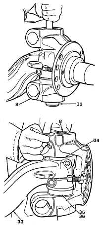
(13)
Use a brass drift and drive kingpins
(32) from knuckles (8).
(14)
Remove knuckles (8) from axle beam
(33). Remove shims (34) from between
knuckles and beam. Check number
and thickness of shims for assembly.
Remove thrust bearings (35) and seals
(36). Discard seals.
(15)
Remove seals (37) from bores of
knuckles (8). Discard seals.
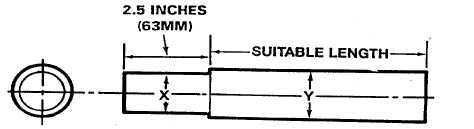
16)
Use a suitable tool or fabricate a tool to
remove bushings, as shown below.
"X" DIAMETER 1.990 INCH
(50.546 MM)
"Y" DIAMETER 2.116 INCH
53.746 MM)
5-238
|