|
| |
TM 5-4210-233-14&P-1
5-23. TURBOCHARGER-Continued
(11)
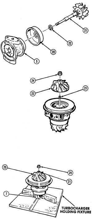
Install turbine shroud wheel (20) on
center housing (5).
(12)
Fill piston ring groove with Dow
Corning High Vacuum Silicon grease
or equivalent (Item 11, Appendix E)
and install piston ring (22) in groove.
(13)
Install turbine wheel shaft (21)
through the shroud wheel and into
center housing (5) Lubricate the
wheel shaft bearing surfaces with oil
(Item 10, Appendix E) prior to
assembly.
(14)
Install compressor wheel (23) on shaft (21).
(15)
Lubricate shaft threads and wheel face
surface that will be under the nut with oil
(Item 10, Appendix E), and install locknut
(24) on shaft (21).
(16)
Place turbine wheel (7) in holding fixture.
CAUTION
Do not put a bending load on shaft
while
tightening
locknut
use
a
double universal socket and tee
handle wrench.
(17)
Tighten locknut (24) to 125-150 lb in
(14 to 17 Nm).
(18)
Loosen locknut (24).
(19)
Inspect faces of locknut (24) and
compressor wheel (23) Make sure
both surfaces are clean and smooth.
(20)
Apply lubricating oil to threads of shaft
(21) and base of locknut (24).
(21)
Retighten locknut (24) to 35 to 55 lb in
(4 to 6 Nm).
5-156
|