Order this information in Print

Order this information on CD-ROM

Download in PDF Format


Click here to make tpub.com your Home Page

Page Title: Assembly (cont)
Back | Up | Next

Click here for a printable version

Google


Web
www.tpub.com

Home


Information Categories
.... Administration
Advancement
Aerographer
Automotive
Aviation
Combat
Construction
Diving
Draftsman
Engineering
Electronics
Food and Cooking
Math
Medical
Music
Nuclear Fundamentals
Photography
Religion
USMC
   
Products
  Educational CD-ROM's
Printed Manuals
Downloadable Books


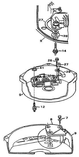
TM 5-4210-233-14&P-1 5-18.  ALTERNATOR-Continued (6) Install terminal (14) through rear of frame (9).  Place washer (39) and connector (27) in position on frame and rectifier bridge.  Secure terminal with nut (40).  Tighten nut to 22 lb in. (2.5 N·m). (7) Install output battery terminal (1 2) through frame (9) and rectifier bridge.   Seat square insulator flange in hole in frame.  Install nut (41) on terminal and tighten finger tight. (8) Install screw (26) through capacitor (29), grounded heat sink, and frame (9).  Tighten screw finger tight. (9) Install screw (27) through capacitor, insulated heat sink and frame (9).   Tighten screw finger tight. (10) Install regulator (8) in frame (9).  Install one regulator screw (7) and tighten finger tight. 5-104

Privacy Statement - Press Release - Copyright Information. - Contact Us - Support Integrated Publishing

Integrated Publishing, Inc. - A (SDVOSB) Service Disabled Veteran Owned Small Business