|
| |
TM 5-4210-233-14&P-1
5-18. ALTERNATOR -Continued
(4)
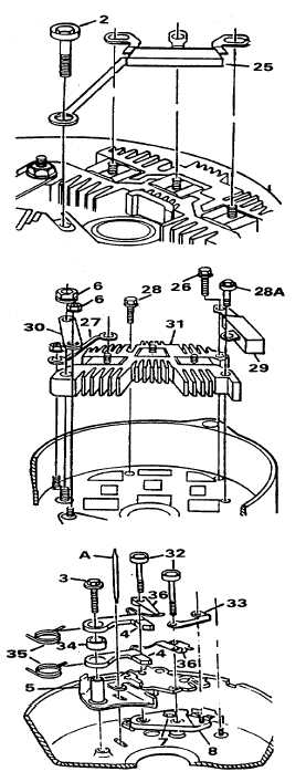
Remove screw (2) and remove diode
trio (25).
(5)
Remove nuts (6) and remove
connectors and 30). Remove three
screws (26, 28 28A). Remove
capacitor (29) and rectifier bridge (31).
(6)
Hold brushes (4) in retracted position
and insert brush pin (A) (Item 93,
Section III, Appendix B) to hold
brushes in position. Remove two
screws (32) and remove stud connector
(33).
(7)
Remove screw (3). Lift brush holder
assembly from frame.
(8)
Remove brush pin (A). Remove
brushes (4) and spacers (34), one at a
time. Keep fingers around springs (35)
to avoid losing springs. It may be
necessary to spread brush 3 lead clips
(36) to disengage tabs. Remove brush
holder (5).
(9)
Remove remaining regulator screw (7)
and remove regulator (8).
5-99
|