|
| |
TM 5-4210-233-14&P-1
5-7. DRIVE SHAFTS, UNIVERSAL JOINTS AND YOKES
This task covers:
a.
Removal of Drive Shafts
e.
Cleaning and Inspection
b. Inspection of Drive Shafts
f.
Installation of Universal Joints
c. Installation of Drive Shafts
g.
Follow-on Maintenance
d. Removal of Universal Joints
TOOLS REQUIRED
MATERIALS/PARTS REQUIRED
Tool Kit, General Mechanics, Automotive
Penetrating Oil (Item 8, Appendix E)
(Appendix B, Section III, Item 1)
High Temperature Grease (Item 15, Appendix E)
Dry Cleaning Solvent (Item 3, Appendix E)
Shop Equipment, Automotive
Lint Free Cloth (Item 42, Appendix E)
Maintenance and Repair
(Appendix B, Section III, Item 4)
EQUIPMENT CONDITION
Main Engine Shutdown (see para 2-12.)
APU Shutdown (see para 2-16.)
Batteries Disconnected (see para 4-114.)
a.
Removal of Drive Shafts.
(1) If the drive shaft universal joint locking
screws and straps are corroded, apply
penetrating oil (Item 8, Appendix E) to ease
disassembly.
(2) Mark all yokes and slip joints before
removal. This will ensure alignment of
components during installation.
(3) Using a hammer and chisel bend down the
ears on the two lockstraps (2) attached to
the yoke opposite the drive shaft to be
removed.
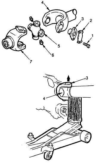
(4) Remove capscrews (1) and lockstraps (2).
(5) Turn the yoke until the bearing plates (3) are
vertically aligned. If necessary, raise the
front or rear axle.
(6) Using a floor jack and a block of wood, jack
the wooden block up until it contacts the
drive shaft end yoke (4) as shown.
(7) Continue to jack the block up until it forces
the upper bearing plate (3) out of the yoke.
(8) Once the upper bearing plate has been
removed, lower the jack and rotate the shaft
a half turn. Remove the second bearing
plate similar to steps 5, 6, and 7.
5-28
|