|
| |
TM 5-4210-233-14&P-1
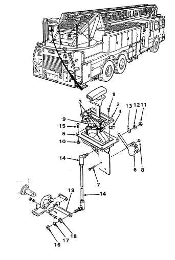
4-185. RUN/LOCK LEVER AND LINKAGE
THIS TASK COVERS:
a.
Removal - Light Bulb
e.
Removal Run/Lock Lever
b.
Installation - Light Bulb
f.
Installation - Run/Lock Lever
c.
Removal - Switch
g.
Adjustment
d.
Installation - Switch
h.
Follow-on Maintenance
TOOLS REQUIRED
EQUIPMENT CONDITION
Tool Kit, General Mechanics, Automotive
Ladder in Transport Position (see para 2-14.)
(Appendix B, Section IiI, Item 1)
Main Engine Shutdown (see para 2-12.)
APU Shutdown (see para 2-16.)
Batteries Disconnected (see para 4-114.)
a.
Removal - Light Bulb.
(1) Remove four screws (1) and lift cover
assembly (2).
(2) Remove two screws (3).
(3) Remove light bulb (4).
b.
Installation - Light Bulb.
(1) Install new light bulb (4).
(2) Install two screws (3).
(3) Install cover assembly (2) and install four
screws (1).
c.
Removal - Switch.
(1) Tag and disconnect wires from switch (6).
(2) Remove two screws (7) and nuts (8).
(3) Remove switch (6).
d.
Installation - Switch.
(1) Install switch (6) and secure with screws (7)
and nuts (8).
(2) Install wires on switch (6).
(3) Listen for the switch to click when the lever
is moved to the run position. Adjust tab on
switch if necessary.
4-475
|