|
| |
TM 5-4210-233-14&P-1
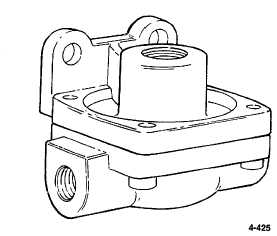
4-150. QUICK RELEASE VALVES (QR-1)
THIS TASK COVERS:
a.
Removal
c.
Follow-on Maintenance
b.
Installation
TOOLS REQUIRED
EQUIPMENT CONDITION
Tool Kit, General Mechanics, Automotive
Main Engine Shutdown (see para 2-12 .)
(Appendix B, Section lll, Item 1)
APU Shutdown (see para 2-16 .)
Batteries Disconnected (see para 4-114 .)
All Air Tanks Drained (see para 4-157 .)
a.
Removal.
NOTE
There are three quick release valves in the brake system. One is
located in-line on the passenger side above the differential of the
forward tandem axle. Another is located in-line on the driver's
side above the differential of the rear tandem axle. The third is
mounted in the center of the first frame crossmem- ber ahead of
the front axle.
NOTE
Refer to locator view in para 4-147 and air schematics in
Appendix G for additional information.
(1) Tag and disconnect air lines from quick release valve.
(2) Remove two mounting bolts and remove valve.
b.
Installation.
(1) Mount quick release valve with exhaust port pointing down.
(2) Install mounting bolts.
(3) Reconnect air lines as identified during removal.
c
Follow-on Maintenance.
(1) Connect batteries
(see para 4-114).
(2) Check for leakage as
described in para 4-147).
4-425
|