|
| |
TM 5-4210-233-14&P-1
5-80. APU VALVES
This task covers:
a.
Adjustment
b.
Follow-on Maintenance
TOOLS REQUIRED
EQUIPMENT CONDITION
Tool Kit, General Mechanics, Automotive
Rocker Arm Cover Removed (see para 5-72.)
(Appendix B, Section III, Item 1)
a.
Adjustment.
NOTE
Check valve clearance when the engine is at room temperature,
about 70 deg. F (21 deg. C).
(1)
Turn the flywheel until the cylinder is on its
compression stroke. Use a socket wrench on the
flywheel screw.
NOTE
To determine if the cylinder is in its compression stroke, observe
the action of the push rod as the engine is rotated in a clockwise
direction. The exhaust valve push rod will be in its lowest
position and the intake valve push rod will be moving downward.
As the piston reaches top dead center, the flywheel timing mark
should be aligned with the timing pointer and the valve push
rods stationary.
(2)
Now turn the flywheel clockwise for an additional 10 to
45 degrees. There is no timing mark for this position, so
it must be estimated. With the piston located in this
position, it will be in its power stroke with both valves
completely closed.
(3)
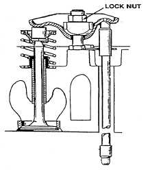
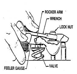
Cylinder head bolt torques should be 44-46 lb ft (60-62
N-m). To change the valve clearance, adjust the locknut
which secures the rocker arm to the cylinder head.
Loosen the locknut to increase clearance and tighten it
to reduce clearance.
(4)
Check valve clearance with a feeler gauge between the
rocker arm and the valve. Increase or reduce the
clearance until the proper gap is established. Correct
valve clearance is 0.01 1-inch (0.28 mm) intake and
0.008-inch (0.20 mm) exhaust.
b.
Follow-on Maintenance.
(1)
Install rocker arm cover (see para 5-72).
5-406
|