|
| |
TM 5-4210-233-14&P-1
5-79. APU GOVERNOR
This task covers:
a.
Removal
d.
Adjustment
b.
Inspection/Repair
e.
Follow-on Maintenance
c.
Installation
TOOLS REQUIRED
EQUIPMENT CONDITION
Tool Kit, General Mechanics, Automotive
APU Removed (see para 4-207.)
(Appendix B, Section III, Item 1)
Gear Cover Removed (see 5-68.)
MATERIALS/PARTS REQUIRED
Grease (Item 53, Appendix E)
a.
Removal.
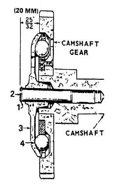
(1)
Remove snap ring (1) from camshaft center pin (2) and
slide cup (3) off. Remove twin governor fly balls (4).
NOTE
Be sure to catch the
ten fly balls that will
fall when the cup is
removed,
b.
Inspection/Repair.
(1)
Replace any fly balls that have flat spots or grooves;
Replace the cup if the race surface is grooved or rough.
The governor cup must be a free spinning fit on the
camshaft center pin, but should be replaced if
excessively loose or wobbly.
(2)
Check the distance the center pin extends from the
camshaft gear; this distance must be 25/32 in. (20 mm)
to give the proper travel distance for the cup. If it is less,
the engine may race; if more, the cup will not hold the
balls properly. If the distance is too great, drive or press
the center pin in. If it too small, replace the pin; it cannot
be removed without damaging its surface.
NOTE
In some cases, if the distance is too small, the head of the
governor cup can be ground to give the necessary 25/32 in. (20
mm) extension.
c.
Installation.
(1)
Tip the front of the unit upward, set the fly balls (4) in their recesses.
(2)
Position governor cup (3) on center pin (2).
(3)
Brush governor ball area with heavy grease (Item 53, Appendix E) and install snap ring (1) on the
center pin (2).
5-404
|