 |
|||
|
|
|||
|
|
|||
| ||||||||||
|
|
 TM 5-4210-233-14&P-1
5-11. ENGINE ASSEMBLY - Continued
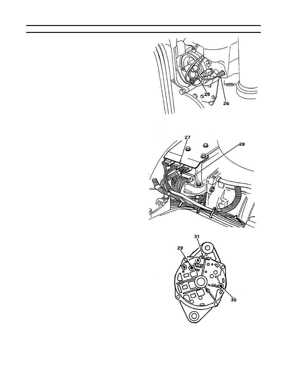
(14) Tag and disconnect two wires (25) from
water temperature sender. (Wire ID nos.
1010M and 1011M.)
(15) Remove sending unit (26) from thermostat
housing.
(16) Tag and disconnect two DDEC wiring
harnesses (27 and 28) from the top-center
and lower right-hand connectors of the
electronic control module on the top front of
the engine.
(17) Locate the Jacobs engine brake wire that
enters the inside of each cylinder head near
the rear of the blower (wire ID numbers
1095L and 1096L). Follow these wires to
the butt splices at the wiring harness on the
driver's side of the engine. Tag and cut the
wires at each butt splice.
(18) Tag and disconnect positive (29) and
negative cables (30) from alternator.
(19) Remove two wire plug (31) from top of
5-44
|
|
Privacy Statement - Press Release - Copyright Information. - Contact Us |
