 |
|||
|
|
|||
|
Page Title:
DRIVER SIDE PUMP CONTROL PANEL-continued |
|
||
| ||||||||||
|
|
 TM 5-4210-233-14&P-1
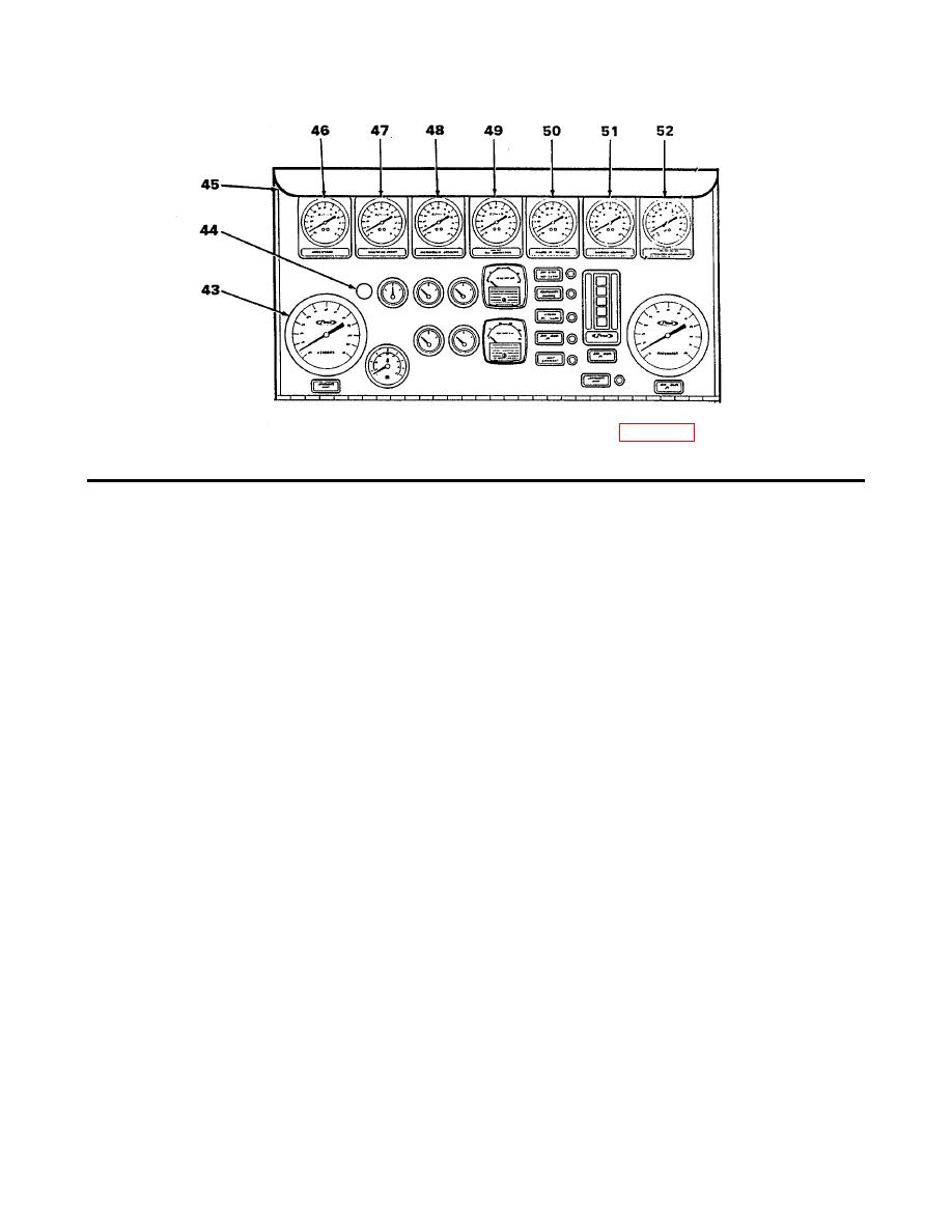
2-3. DRIVER SIDE PUMP CONTROL PANEL- Continued
NOTE: Items 39, 40, 41, and 42 are illustrated on page 2-15.
ITEM
CONTROL/INDICATOR
FUNCTION
39
MANUAL PUMP SHIFT Control
Engages and disengages fire pump. Pull for driving mode,
push for pumping operations.
40
ELECTRIC SHIFT Control
Pull to disengage electric pump shift.
41
FRONT SUCTION Control Wheel
Opens and closes front suction valve.
42
PuIl-Out Tread Plate
Provides platform for operator. Pull handle to release lock.
Pull shelf out until it locks.
43
VACUUM Gauge
Indicates vacuum in suction system in psi.
44
Audio Alarm
Emits electronic signal when transmission oil temperature
is above the maximum.
45
Panel Lights
Illuminate pump control panel when PANEL LIGHT switch
is ON.
46
NO. 1 CROSSLAY Gauge
Indicates water pressure in the No. 1 crosslay (psi).
47
NO. 2 CROSSLAY Gauge
Indicates water pressure in the No. 2 crosslay (psi).
48
NO. 1 DISCHARGE Gauge
Indicates water pressure at the No. 1 discharge (psi).
49
NO. 2 DISCHARGE Gauge
Indicates water pressure at the No. 2 discharge (psi).
50
NO. 3 DISCHARGE Gauge
Indicates water pressure at the No. 3 discharge (psi).
51
NO. 4 DISCHARGE Gauge
Indicates water pressure at the No. 4 discharge (psi).
52
AERIAL DISCHARGE Gauge
Indicates water pressure at the aerial discharge (psi).
2-16
|
|
Privacy Statement - Press Release - Copyright Information. - Contact Us |
