|
| |
TRUCK SERVICE MANUAL
TM 5-4210-230-14&P-1
STEERING GEAR
Fig. 39
Fig. 40
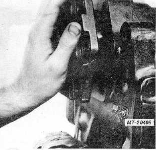
37.
Assemble six special bolts (61) and torque to 298-
325 Nm (220-240 ft.lbs.).
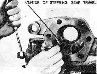
38.
Adjust side cover adjusting screw (51) to provide a
2.6-3.2 Nm (23-28 in.lbs.) torque at worm shaft (17)
as steering gear is moved 90 deg. each side of
center. Back out the adjusting screw one turn and
note torque required to move thru 90 deg. each side
of center. Move adjusting screw in to provide a rise
in torque of .23-.45 Nm (2-4 in.lbs.) at a point within
45 deg. each side of center. After tightening nut (59)
to 54-61 Nm (40-45 ft.lbs.) torque to rotate worm
shaft must not exceed 2.9 Nm (26 in.lbs.) at any
point in steering gear travel (Fig. 41).
Fig. 41
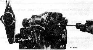
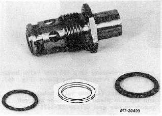
39.
Assemble back-up washer (24), two-piece seal (23)
and seal (25) into trunnion cover (26). Assemble
two-piece seal (23) with "oil side" towards housing
(20).
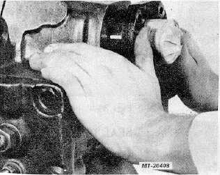
40.
Cover serrations on sector shaft (50) with tape and
assemble trunnion cover (26) (Fig. 42).
Fig. 42
Fig. 43
CTS-2717 Page 13
PRINTED IN UNITED STATES OF AMERICA
|