|
| |
TRUCK SERVICE MANUAL
TM 5-4210-230-14&P-1
STEERING GEAR
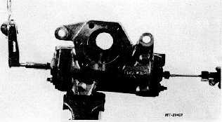
Fig. 31
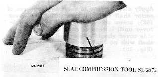
24. Apply, clean grease to seal ring (13) areas of valve
sleeve (15).
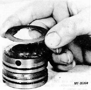
25.
Apply clean grease to end of valve sleeve (15) and
assemble thrust washer (11) onto end of valve
sleeve, grease must hold thrust washer in place (Fig.
32).
Fig. 32
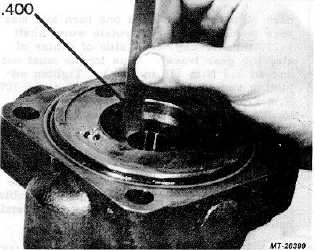
26.
Assemble valve sleeve (15) with thrust washer
attached down into valve housing (9). When valve
sleeve is down into place in valve housing, it should
measure approximately 10.2 mm (.4 in.) from face of
valve housing to face of valve sleeve (Fig. 33).
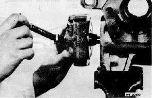
27.
Align timing marks on valve sleeve (15) and worm
shaft (17) and assemble valve housing (9) onto worm
shaft. Make sure drive ring (16) teeth engage
notches in valve sleeve (15). Use a box end wrench
to rotate worm shaft to pull valve housing (9) down
against housing (20)(Fig. 34).
Fig. 33
Fig. 34
28.
Assemble four bolts (1) into housing (20) and torque
to 142-156 Nm (105-115 ft.lbs.).
Fig. 35
29.
With rack piston (31) near center of steering gear
travel, screw adjusting screw (39) into solid height.
14 Nm (10 ft.lbs.) maximum
CTS-2717 Page 11
PRINTED IN UNITED STATES OF AMERICA
|