|
| |
TRUCK SERVICE MANUAL
TM 5-4210-230-14&P-1
STEERING GEAR
DESCRIPTION
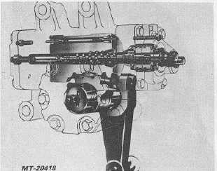
This steering gear (Fig. 1) is a fully integral power
steering unit incorporating a hydraulic control valve, a
hydraulic power cylinder and a manual steering
mechanism into a single compact package. The control
valve is a rotary design which combines simplicity of
construction with desirable performance characteristics.
Flow of oil from an engine driven pump is directed to the
power cylinder by the control valve.
Fig. 2
DISASSEMBLY (For callouts, refer to Fig. 1)
Thoroughly clean off all outside dirt before
disconnecting hoses. (Port holes should be plugged
immediately after disconnecting hoses and before
removing from the vehicle.)
All parts should be cleaned in clear, clean solvent
and blown dry with air. Keep each part separate to
avoid nicks and burrs.
IMPORTANT
Avoid wiping valve parts with cloth, as lint may
actually cause binding and sticking of the
closely fitted parts. Never steam clean or high
pressure
wash
hydraulic
steering
gear
assemblies. Do not force or abuse closely fitted
parts, as damage may result.
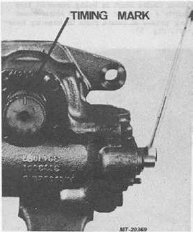
1.
Position steering gear in a vise with worm shaft
(17) in a horizontal position. Check timing mark
located on end of sector shaft (50), position this
mark in vertical direction with steering gear in
center of steering gear travel.
Fig. 3
2.
Remove any paint or corrosion from serrated end
of sector shaft (50) and loosen jam nut (59) on
sector shaft adjusting screw (51).
3.
To drain steering gear fluid remove six "special
ring head" bolts (61) from side cover (58). These
bolts have a special ring located on bolt head for
sealing purposes, if these bolts are replaced, they
must be replaced with same "special" type and
length of bolt.
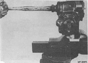
4.
Remove side cover (58) and sector shaft (50). A
soft hammer or wooden handle may be used to
remove sector shaft (Fig. 4).
Fig. 4
CTS-2717 Page 3
PRINTED IN UNITED STATES OF AMERICA
|