|
| |
TRUCK SERVICE MANUAL
TM 5-4210-230-14&P-1
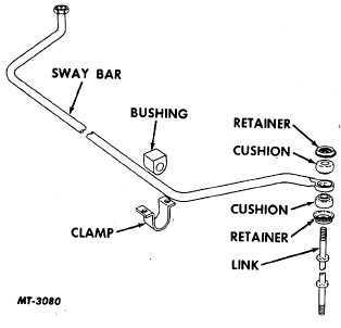
Fig. 7 Front Sway Bar
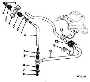
Fig. 8. Rear Sway Bar
Legend for Fig. 8
Key
Description
1
NUT
2
WASHER
3
BUSHING
4
BRACKET
5
SPACER
6
LINK, Sway Bar
7
RETAINER, Cushion
8
CUSHION
9
NUT
10
SWAY BAR
11
BRACKET
12
BUSHING
13
BRACKET
Sway bars are available for both front (Fig. 7) and
rear (Fig. 8) suspension applications.
Simple in construction, these bars perform their
stabilizing effect by twisting when spring height at
opposite wheels becomes unequal. For example, if the
wheel on one side drops into a chuck hole, the spring on
that same side expands. At the same time the sway bar
tends to expand the opposite spring and lift the truck.
Failing to do this, the bar twists and lessens the shock of
the wheel dropping.
In like manner, if the wheel on one side hits an
obstacle, the spring on that side compresses. The sway
bar tends to compress the opposite spring and hold the
truck down. Failing to do this, the sway bar twists and
lessens the shock. This resistance to twisting in the
sway bar is particularly useful in limiting sway or roll
when the truck is rounding a curve or when it suddenly
encounters a strong cross wind.
No service is necessary on the sway bar other
than a periodic inspection to see that mounting parts
remain secure. Rubber bushings should be replaced
when they become deteriorated or permit metal to metal
contact. Keep mounting bolts tight.
CTS-2680S Chapter I Page 6
PRINTED IN UNITED STATES OF AMERICA
|