|
| |
ENGINE DIVISION SERVICE MANUAL
TM 5-4210-230-14&P-1
NON-SCHEDULED MAINTENANCE OPERATIONS
DECELERATION THROTTLE MODULATOR (DTM)
SYSTEM
Deceleration Throttle Modulator
System Operation
The deceleration throttle modulator system consists
basically of a vacuum operated throttle modulator unit on the
carburetor, a solenoid vacuum valve and engine speed sensor
unit.
Normally an engine will emit relatively high levels of
unburned hydro-carbons during "closed throttle" deceleration.
This is because the intake of fuel/air mixture is not sufficient
to support complete combustion and the engine "misfires"
resulting in fuel being passed through the engine unburned.
The deceleration throttle modulator system overcomes this
condition by maintaining a slightly greater throttle opening
(high idle) during initial deceleration which permits intake of
just enough additional fuel/air mixture to promote combustion
and eliminate misfire.
The engine speed sensor is calibrated to activate or
deactivate (extend or retract) the throttle modulator unit at
approximately 1850 RPM engine speed. Operation of the
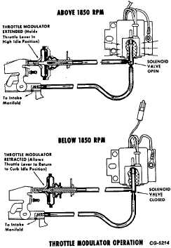
throttle modulator is illustrated in Fig. 60.
Above 1850 RPM engine speed, the solenoid vacuum
valve is activated (held open) by electrical current from the
engine speed sensor unit. This permits manifold vacuum to
act upon the diaphragm of the throttle modulator unit
extending the modulator unit to the high idle position. Upon
deceleration, the returning carburetor throttle level contacts
the extended modulator, thus holding the throttle in high idle
position.
When engine speed drops below 1850 RPM, the speed
sensor unit deactivates the solenoid vacuum valve allowing
the valve to close and bleed the vacuum from the throttle
modulator diaphragm chamber. This permits the diaphragm
spring to retract the modulator unit and allow the throttle lever
to return to normal curb idle position.
Check Deceleration Throttle Modulator
Operation, replace if necessary.
a.
Check modulator for free operation by grasping
modulator by large diameter of the plastic
housing and pulling (without twisting) toward throttle
lever. Plastic housing should move freely against
internal spring force for about 6 mm (¼ "). Modulator
should be replaced if it does not move freely or does
not return rapidly to fully retracted position (Fig. 60).
b.
Check throttle modulator speed setting and adjust, if
necessary.
(1)
Connect tachometer to engine.
(2)
Start and operate engine until normal operating
temperatures are reached.
Fig. 60 Throttle Modulator Operation
(3)
Disconnect vacuum hose from modulator and
manually apply vacuum to modulator (Fig. 61). If
modulator does not extend, unit is faulty and must be
replaced. Allow throttle to close against extended
modulator.
(4)
Observe engine speed. For proper speed, see
Emission Control Tune-Up Specifications.
CGES-215 Page 35
PRINTED IN UNITED STATES OF AMERICA
|