|
| |
ENGINE DIVISION SERVICE MANUAL
TM 5-4210-230-14&P-1
TROUBLE SHOOTING
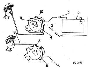
5. Apply battery voltage to solenoid valve side of cable
as shown. The solenoid valve should make a slight
noise or movement felt when current is applied and
released indicating the solenoid valve plunger is
operating.
a.
If the solenoid is operating properly, proceed to step
6.
Figure 68. Step 6
1. To Solenoid Valve Case
6.
“A” Port Closed
2. Battery, 12 Volt
7.
Air Output
3. Solenoid Cable
8.
Use Vacuum Hose for Air
4. “A” Port Open
Input Test
5. “B” Port Open
9.
Air Output 10. “B” Port
Closed
b. If the noise is not heard or movement felt,
remove solenoid valve and cover assembly
from carburetor. Make a resistance check
with an ohmmeter from the solenoid valve
cable to the valve assembly case as shown.
The ohmmeter should read approximately 50
+ 10 ohms. If resistance is zero or a very high
reading, the solenoid valve assembly must be
replaced.
c. If resistance is 50 + 10 ohms, the solenoid
valve windings are good. Remove solenoid
valve from cover. Check to see if valve seat is
sticking, keeping solenoid valve plunger from
operating.
6. If Steps 1 through 5 have proved that the electrical
portion of governor system is operating properly, the
trouble must be in the cover vacuum passages on
the carburetor.
a. With solenoid valve assembled to cover, apply air
through a small diameter hose as shown to port
“A,” then port “B” to insure passages are clear.
With battery voltage applied: Port “B” should be
closed. Port “A” should be open. Without battery
voltage applied: Port “B” should be open. Port “A”
should be closed.
b. If solenoid valve plunger is not seating properly,
replace solenoid valve.
c. If vacuum passages in the cover are clogged,
clean (cover only) with commercial carburetor
cleaning solvent.
7.
Some carburetor malfunctions that are not a part of the
EVM governor system may affect governor action. These
malfunctions can be corrected by using the CLEANING
AND INSPECTION portion of this service manual.
SECONDARY CONTROL VALVE TROUBLE SHOOTING
Malfunction of the secondary control valve can cause
fluctuation of engine speed (“surging”) when the governor is in
effect or failure of the governor to limit engine speed.
Because calibration of the control valve requires special
equipment, the secondary diaphragm cover (with secondary
control valve) is assembled, calibrated and sealed at the factory
and furnished for service only as an assembly. Control valve
components are not serviced separately.
Outlined in the following paragraphs are procedures for
testing the secondary control valve. These procedures are used to
determine if the control valve is satisfactory or if it should be
replaced.
Bench Test
The following “bench” test procedure can be used to
check functioning of the control valve. It is recommended that this
check be made at the time of carburetor overhaul or if improper
valve operation is suspected.
1. Connect a controllable vacuum source to the vacuum
inlet of the control valve diaphragm chamber, as shown in
Fig. 69. (Distributor tester SE-1925 or SE-1979 can be
used as a vacuum source.) Apply 6 inches of vacuum
CGES-125-T Page 43
PRINTED IN UNITED STATES OF AMERICA
ENGINE DIVISION SERVICE MANUAL
TM 5-4210-230-14&P-1
TROUBLE SHOOTING
to the diaphragm chamber. If vacuum holds, the control valve
diaphragm is satisfactory. If vacuum cannot be maintained,
|

