|
| |
TRUCK SERVICE MANUAL
TM 5-4210-230-14&P-1
REASSEMBLY
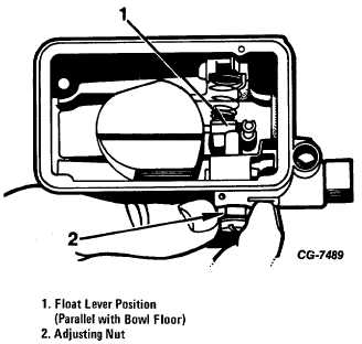
Figure 48 Bench Adjustment of Fuel Bowl Float
12. The float is made of cellular plastic material; its buoyancy
is unaffected by leaks (sometimes experienced with hollow
floats) or absorption. While the final fuel filter adjustment is
made with the carburetor installed on the engine, a bench
adjustment can be made before installing bowl as follows:
a. Loosen lock screw enough to allow adjusting nut to be
turned.
b. With fuel bowl inverted turn adjusting nut until float lever is
parallel with floor of bowl (Fig. 48). Tighten lock screw.
13. Install fuel bowl screw gaskets on fuel bowl screws. This
will prevent threads from shaving off gasket particles into fuel
bowl.
14. Position metering body gasket (see Fig. 49) on the
dowels on the back of the metering body. Assemble metering
body on main body and fuel bowl on metering body. Insert
four fuel bowl screws and tighten to 25-30 inch pounds.
15. When positioning fuel bowl the accelerating pump lever
must be slightly depressed to clear the diaphragm pump
lever. When spring loaded bowl screws are used the following
procedure should be used:
Tighten each spring loaded bowl screw by rotating screw head
until screw assembly bottoms in main body.
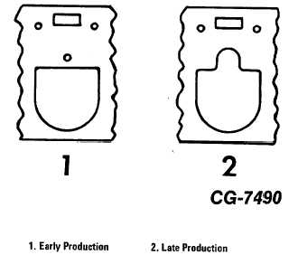
Figure 49 Both Metering Body Gaskets are Furnished in
Carburetor Rebuild Kits
Bottoming of screw assembly is accomplished when screw
head "springs back" about one quarter (¼ ) turn when screw
driver is removed from slot. Excessive rotation of screw head
can destroy spring.
16. Apply Vaseline to the fuel transfer tube "O" ring seals and
place the seals against the flanges on both ends of the fuel
transfer tube and install one end of the tube in the primary fuel
bowl.
Secondary Fuel Bowl and Metering Block:
17. Assemble the secondary fuel bowl by following Steps 9
through 12. As a preliminary secondary float adjustment,
adjust the float so that the top of the float is parallel to the
bowl floor with the bowl in an inverted position (Fig. 48).
18. Install the following parts in the secondary metering
block.
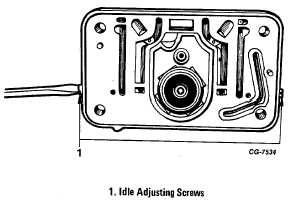
Figure 50 Secondary Metering Block
CGES-125-T Page 32
PRINTED IN UNITED STATES OF AMERICA
|