|
| |
TRUCK SERVICE MANUAL
TM 5-4210-230-14&P-1
REASSEMBLY
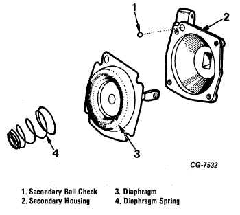
4. Drop the secondary vacuum ball check in the vacuum
passage in the secondary diaphragm housing (Fig. 45).
5. Because calibration of the control valve requires special
equipment, the secondary diaphragm cover (with secondary
control valve) is assembled, calibrated and sealed at the
factory and furnished for service only as an assembly.
Control valve components are not serviced separately.
Figure 45 Installing Secondary Diaphragm
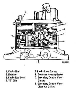
Figure 46 Components Location on Main Body
6. Place the gasket on the secondary vacuum and clean air
passage openings on the main body (Fig. 46). Lay the
diaphragm housing in position on the main body and install
the lock washers and retaining screws.
7. Place the choke rod lever spring on the lever with the end
of the spring with largest hook on the lever (Fig. 46).
8. Place the choke rod lever and spring assembly in position
on the main body with the other end of the spring fitting in the
groove in the main body. Install the choke lever retainer (Fig.
46).
9. Secure the choke rod to the lever with a pin retainer (Fig.
46).
10. Invert the main body and position the throttle body gasket
on the main body. Slide the secondary diaphragm rod onto
the operating lever as the throttle body is placed into position.
Install the diaphragm operating rod retainer.
11. Install the throttle body to main body screws and lock
washers.
12. Install the air cleaner anchor stud.
13. Position the governor housing gaskets on the main body.
Install the governor body seal on the governor housing, then
slide the housing on the throttle shaft so that with the choke
plate closed the protruding stud on the fast idle cam lever is in
the slot of the choke rod lever tang. As the governor body is
placed into position, insert the end of the throttle shaft into the
governor (Fig. 46).
14. Install the governor housing retaining screws and the
governor lever lock washer and nut. The governor lever
should hold the primary throttle plates wide open.
15. Be sure the primary throttle plates are closed and the
choke plate is open. Adjust fast idle screw to the correct
specification. See fast idle procedure setting.
16. Install the governor housing cover and the choke swivel.
The choke swivel should open and close the choke plate.
17. Install seal wire through opposite screws on cover insert
seal and crimp.
CGES-125-T Page 30
PRINTED IN UNITED STATES OF AMERICA
|