|
| |
TRUCK GROUP SERVICE MANUAL
TM 5-4210-230-14&P-1
GENERAL
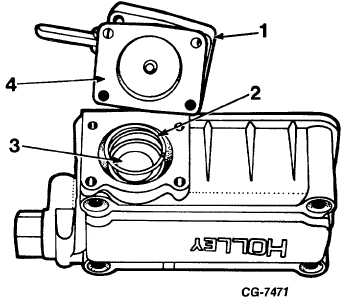
Figure 15 Acceleration Pump Assembly (shown with plastic
pump inlet valve used on later model carburetors).
1. Diaphragm Cover
3. Plastic Valve
2. Diaphragm Return
4. Diaphragm Assembly
Spring
diaphragm. Hydraulic pressure forces fuel in the pump cavity
and channels past the needle check valve and out the pump
discharge nozzles into the air stream.
Upon return of the throttle lever toward idle position, the
diaphragm spring returns the diaphragm and the resultant
pressure differential causes the discharge valve to close and the
inlet ball or plastic check valve to open, allowing the pump
cavity to refill with fuel from the bowl.
Choke System
The function of the choke system is to provide a rich
air/fuel mixture necessary for cold starting and engine warm-up
(Fig. 16).
The choke plate, which is manually operated on governor
type carburetors, may be closed during the engine cranking
period and partially opened during the warm-up period. This
induces a low pressure on the fuel metering system, causing
both the main and idle systems to discharge more fuel
producing mixtures rich enough to insure smooth power as the
engine warms up.
During the full choke period, the high point of the fast idle
cam is in contact with the fast idle adjusting screw which sets
the throttle plates at a predetermined angle causing engineRPM
to be high upon starting. As the choke is manually opened,
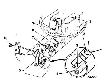
Figure 16 Manual Choke System
1. Choke Plate
6. Choke Cable
2. Fast Idle Adjusting Screw 7. Fast Idle Cam
3. Fast Idle Pin
8. Choke Rod Lever
4. Throttle Shaft
9. Choke Rod
5. Choke Lever
the cam moves rotationally away from the fast idle adjusting
screw allowing the engine to resume its normal idle speed
setting.
Throttle Modulator-1970-1971 Vehicles Under 6000 Lbs.
GVW
To provide acceptable exhaust emission levels, the
carburetors of certain vehicles require the use of a throttle
modulator.
The throttle modulator is vacuum operated and functions
above a predetermined road speed to aid in the control of
exhaust emission during engine deceleration.
Fig. 17 shows throttle modulator diagram. A speed
sensor (spinner valve) is driven by the speedometer cable. A
vacuum source and bleed line are piped into the speed sensor.
The sensor is designed to open the bleed line to the vacuum
source when vehicle road speed is below the predetermined
cutoff speed (approximately 24 MPH). As long as the bleed line
is open, no vacuum is available to extend the modulator.
When the vehicle passes the road speed cutoff point, the
bleed line is closed, making vacuum available to actuate the
modulator.
CGES-125-T Page 10
PRINTED IN UNITED STATES OF AMERICA
|