|
| |
ENGINE DIVISION SERVICE MANUAL
TM 5-4210-230-14&P-1
GENERAL
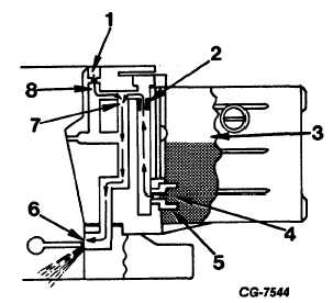
Figure 7 Idle System Fuel Air Flow
Primary Side
1. Idle Air Bleed
5. Main Jet
2. Idle Feed Restriction
6. Idle Discharge Slot
3. Fuel Bowl
7. Fuel/Air Flow
4. Fuel Flow
8. Air Flow
discharged through the idle discharge hole into the throttle
bores below the secondary throttle plates. As the throttle plates
are opened fuel-air is discharged into the throttle bores from the
idle transfer slots. (Fig. 8)
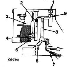
Figure 8 Idle System Fuel Air Flow
Secondary Side
1. Idle Air Bleed
6. Idle Adjusting Needle
2. Idle Feed Restriction
7. Idle Discharge Hole
3. Fuel Bowl
8. Fuel/Air Flow
4. Fuel Flow
9. Air Flow
5. Main Jet
Main Metering System
As the throttle plates open in response to speed and/or
load demand, the air flow through the carburetor main venturi
increases in velocity, inducing an increased depression on the
main metering system, causing air/fuel mixture to flow from the
main discharge nozzle. The flow from the idle system gradually
decreases and reverses as the carburetor approaches a wide
open throttle condition (Fig. 9).
In the main metering system, the fuel flows from the fuel
bowl through the main metering jet which meters the fuel into
the main well. The fuel mixes with air inducted through the
main well air bleed in the side of the well. The emulsion created
then passes through the discharge channel and is discharged
into the carburetor venturi by the discharge nozzle.
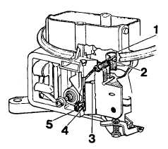
Figure 9 Main Metering Fuel Air Flow
1. Booster Venturi
5. Main Jet
2. Discharge Nozzle
6. High Speed Air Bleed
3. Main Well Air Bleed
7. Booster Venturi
4. Main Well
CGES-125-T Page 7
PRINTED IN UNITED STATES OF AMERICA
|