|
| |
TRUCK SERVICE MANUAL
TM 5-4210-230-14&P-1
FUEL SYSTEM
After servicing filter element, reset signal (red band) by
pressing reset button and then releasing. This allows red signal
band to again rise above window.
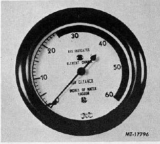
Where a direct reading air cleaner restriction gauge (Fig.
10) is used, the maximum allowable restriction is 25 inches of
water measured at the air cleaner outlet during any phase of
engine operation. When this happens, filter element service is
required.
Fig. 10 Air Cleaner Restriction Gauge
SERVICING
NOTE: Refer to the applicable owner's manual to obtain
recommended mileage intervals for air cleaner element
replacement and service.
Modulated Dry Type Air Cleaner
Service of modulated dry type air cleaner paper element
is limited, consisting mainly of checking the element for
punctures or splits by looking through element toward light.
Tap element-lightly on a flat surface or use low air pressure to
remove dirt particles. Do not wash or oil element.
Operation of the vacuum chamber and temperature
sensor may be checked by conducting the following tests.
NOTE: Tests should be conducted with engine started
from cold and ambient temperature of vehicle being not
less than 40 F. Air cleaner must have all hoses, piping
and cover in place. No leaks permitted.
1.
With engine off inlet tube damper should be in full
down position to close heat tube inlet pipe from
exhaust manifold stove. Damper position can be
determined by looking in end of inlet tube and should
be parallel to tube bottom. If damper assembly is not
in the correct position, vacuum chamber should be
removed and damper movement loosened. Replace
vacuum chamber and recheck damper position.
2.
Start engine and note that damper has rotated up to
close off cold air inlet. Observe damper position by
looking in the inlet tube. If damper did not immediately
close cold air inlet, shut off engine and disconnect the
two hoses from sensor. Connect the two hose ends
together using suitable tubing.
Restart engine and again check damper location. If
damper fully closes cold air inlet, temperature sensor
is defective and must be replaced. If damper did not
close cold air inlet, sensor is okay but damper has bind
or vacuum chamber is defective. Remove vacuum
chamber and check damper for free movement. If
damper moves freely, replace vacuum chamber.
3.
After a cold start operate engine for 10 minutes at
medium RPM. When engine is at normal operating
temperature, slow engine to idle and observe position
of inlet tube damper. If damper has not rotated all or
part way down to allow some cold air to enter inlet
tube, replace temperature sensor.
Vacuum Chamber Replacement (Fig. 11)
Vacuum chamber is replaced by bending tab nearest
inlet tube entrance down from inside of tube. Disconnect
vacuum hose and lift vacuum chamber, sliding rear tab out of
its slot and disengaging damper hook from damper.
The new chamber is attached by engaging hook in
damper, sliding rear tab into its slot and fitting front tab into
place. A spring preload should be felt when vacuum chamber is
pressed firmly against top of inlet tube. If no preload is felt,
check the installation or
CTS-2056N Page 5
PRINTED IN UNITED STATES OF AMERICA
|