|
| |
ENGINE DIVISION SERVICE MANUAL
TM 5-4210-230-14&P-1
ENGINE
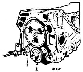
Fig. 145 Checking Camshaft and Crankshaft Gear
Backlash
1. Dial indicator
3. Crankshaft gear
2. Camshaft gear
12. Turn the crankshaft so No. 1 crankpin is at the top of its
stroke. Coat the cylinder bores, crankshaft journals,
pistons, piston pins and piston rings with engine oil.
Insert the piston into the ring compressor and install the
piston assembly into its respective cylinder bore, Figure
146. Make certain the odd numbers stamped on the
connecting rods (1-3-5-7) are facing toward the right side
of the cylinder block, while even numbers (2-4-6-8) are
facing the left side of the cylinder block. Install the
connecting rod bearings and caps, coating each bearing
shell surface on both sides with engine oil. The
numbered side of the cap must match and be on the
numbered side of the rod.
NOTE: If the connecting rods and bearing caps are
properly installed, the large chamfer side of the rod
and cap will be to the fillet side of the crankpin.
Install new bearing cap bolts, washers and nuts and
tighten to the specified tortue as shown in "Torque
Chart."
13. Follow the procedure outlined in Step 12 for the
remaining connecting rods and pistons.
14. Recheck connecting rod end play using a feeler gauge as
outlined under "Fitting Connecting Rod Bearings" in
CLEANING, INSPECTION AND RECONDITIONING.
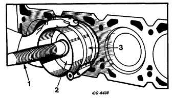
Fig. 146 Installation of Piston in Cylinder Block
1. Hammer handle
3. Ring Compressor
2. Piston
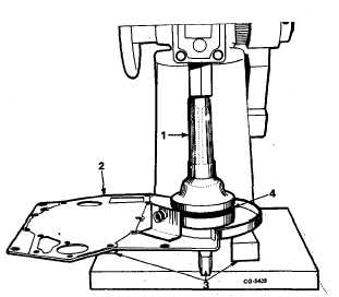
15. Press new oil seal in engine front cover using SE-1949
installer and support blocks, Figure 147. Install oil seal
flush to .010" below front face of front cover.
Fig. 147 Pressing New Seal in Engine Front Cover Using SE-
1949 Installer and Support Blocks
1. Installer
3. Support blocks
2. Front cover
4. Oil seal
CGES-210 Page 59
PRINTED IN UNITED STATES OF AMERICA
|