|
| |
ENGINE DIVISION SERVICE MANUAL
TM 5-4210-230-14&P-1
ENGINE
Apply the same procedure to the remaining bearing caps.
Recheck the crankshaft end play as outlined under
"Fitting Main Bearings."
8.
Install flywheel housing on crankcase. Torque bolts to
specified torque. See "Torque Chart." Install oil pressure
sending unit.
9.
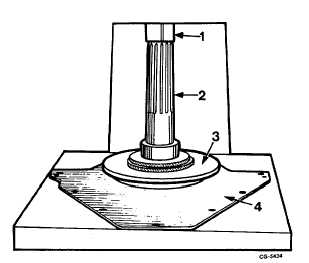
Press crankshaft rear oil seal into retainer plate using SE-
1905 installer and 5-1/4" O.D. adapter, Figure 142. The
seal must be installed from the crankcase side of the
retainer flush with the seal bore inner surface.
Fig. 142 Pressing Rear Oil Seal into Retaining Plate Using SE-
1905 Installer with 5-1/4" O.D. Adapter
1. Press ram
3. Adapter
2. Installer
4. Retainer
NOTE: Wipe inside of retainer plate clean to insure a
proper fit.
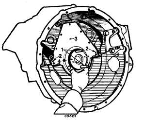
10. Use SE-1942-2 Pilot to install rear oil seal and retainer
with gasket on crankcase, Figure 143. Dowel pins are
provided for proper alignment. Torque bolts to specified
torque. See "Torque Chart."
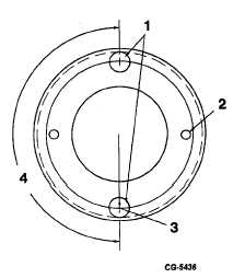
NOTE: Drill two 25/64" diameter holes in SE-1942-2 Pilot
according to the dimensions on Figure 144 to accept two
3/8" diameter x 4" pilot studs. The pilot studs serve as a
safety measure to retain the pilot on the crankshaft where
seal replacement is performed with engine in the vehicle.
Fig. 143 Installing Retainer with Rear Oil Seal Using
SE-1942-2 Pilot
1. Pilot studs
3. Retainer
2. Dowel pins
4. Pilot
Fig. 144 Dimensions for Rework of SE-1942-2 Pilot
1. 25/64" dia. holes
2. Existing guide pin holes
3. 1.59375R
4. 180°
11. Rotate the crankshaft and camshaft to determine that the
gears do not bind or interfere. With the use of a dial
indicator, Figure 145, check the backlash. See
"Specifications" for backlash.
CGES-210 Page 58
PRINTED IN UNITED STATES OF AMERICA
|