|
| |
ENGINE DIVISION SERVICE MANUAL
TM 5-4210-230-14&P-1
ENGINE
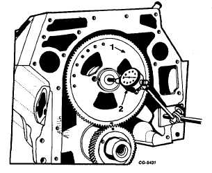
Fig. 139 Checking Camshaft End Play
1. Camshaft gear
2. Dial indicator
6.
Wipe the backs of the cylinder block half of the bearings,
making sure the dirt is removed. Lubricate the block half
of the bearings on both sides with a light film of engine
oil. Place the bearing shell halves in position in the bore
of the cylinder block, making sure the bearing shells are
fully seated, the oil holes in the bearing shells line up with
the oil holes in the cylinder block and the locking tangs on
the bearings fit into the recesses. Follow the same
procedure and place the bearing shell halves in the
bearing caps. Place a film of engine oil on both sides of
the shell surfaces and
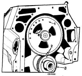
Fig. 140 Aligning Timing Marks on Camshaft and Crank- shaft
Gears
1.
Camshaft gear
2.
Timing marks
3.
Crankshaft gear
install the crankshaft, aligning itself in the bearing while,
at the same time, aligning the timing marks of both the
camshaft and crankshaft gears, Figure 140
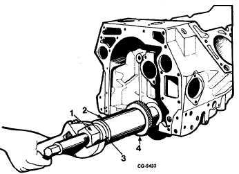
NOTE: If crankshaft gear has been removed, it may be
installed with the crankshaft in the engine using SE-1900
Installer, with SE-1900-18 Adapter and thrust bearing to
reduce friction, Figure 141.
7.
Place the bearing caps and bearing lower halves over the
crankshaft journals. Be sure the bearing caps are
properly installed with the number toward the left side of
the crankcase and the arrow, pointing toward the front of
the engine. Use new selflocking bolts for installing the
bearing caps. Finger tighten the bearing caps. Using a
soft hammer, tap the number 1, 2 and 4 bearing caps
until the rear machined faces of the caps are flush with
the machined faces of the crankcase.
Fig. 141 Installing Crankshaft Gear with SE-1900 Installer and
SE-1900-18 Adapter
1. Nut
3. Thrust bearing
2. Sleeve
4. Gear
Repeat the same operation for bearing cap number 5 only
aligning the front face of the cap with the crankcase. The
number 3 bearing rear thrust flanges must be flush with each
other. Aligning caps in this manner will assure proper cap
location. Check this alignment at both sides (left and right) of
the bearing cap. Torque the bolts to specified torque using a
tension wrench. See "Torque Chart."
CGES-210 Page 57
PRINTED IN UNITED STATES OF AMERICA
|