|
| |
ENGINE DIVISION SERVICE MANUAL
TM 5-4210-230-14&P-1
ENGINE
After
removing
the
plunger,
the
check
valve
assembly may be found to be loose on the plunger. Care
should be taken so the small, flat check valve and valve
retainer spring are not lost. If the check valve assembly stays
attached to the plunger, it would be best to leave it in this
position.
IV.
Servicing the Lifter
The following is the service procedure to be followed in
servicing hydraulic lifters:
A
Immerse the unit in carburetor or other suitable
solvent to remove excess engine oil and soften
varnish deposits.
B.
To avoid mixing plungers and cylinders, take one
lifter apart at a time and complete all servicing before
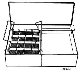
working on another. However, if tray SE-1892,
Figure 121, is available for keeping plungers and
cylinders
together,
all
lifters
may
then
be
disassembled at the same time.
Fig. 121 Hydraulic Lifter Tray SE-1892
C.
Wash all parts in solvent and clean all varnish from
the plunger and inside diameter of the cylinder.
D.
Inspect the plunger and cylinder walls for scratches.
Look for nicks on the valve seat and examine the
condition of the lifter face. Check for plugged oil
holes.
E.
Try the plunger for free fit in the cylinder. F.
Reassemble all parts in proper sequence Figure 120.
NOTE:
The valve lifter body is to be filled 1/3 full
with clean kerosene before assembly of
component parts. The parts are to be
prelubricated with clean kerosene before
assembly. Use of kerosene in place of
engine oils provides a faster leakdown and
rapid expelling of trapped air in the lifter
assembly, thus eliminating the possibility
of damage to the valve train when
installing the push rods and rocker arm
shaft assembly. Engine oil will dilute the
kerosene in the lifters as soon as the
engine is operated for a short period.
G.
After the unit has been washed thoroughly, determine
whether the leakage past the plunger and cylinder is
correct and if the check valve is functioning correctly.
This may be done using one of the two following
methods:
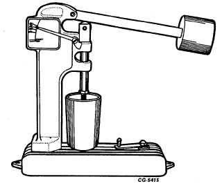
1. The SE-1893 leakdown tester, Figure 122, may be
used for checking the leakdown rate if available.
Instructions which accompany the tester should be
followed.
Fig. 122 SE-1893 Tester Used for Checking Leakdown Rate
of Tappet
2.
If the leakdown tester is not available, a finger check
method can be used. In order to check a unit in this
manner, make sure there is no lubricating oil on the
cylinder or plunger such as immediately after
washing in solvent. With the cylinder held in one
hand, start the
CGES-210 Page 47
PRINTED IN UNITED STATES OF AMERICA
|