|
| |
ENGINE DIVISION SERVICE MANUAL
TM 5-4210-230-14&P-1
ENGINE
spring retainer. On the intake valves, install the valve spring
seat, valve stem seal, valve spring, damper and spring
retainer.
NOTE:
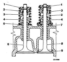
Care should be taken to see the valve stem
seals are installed correctly. If they are
not, their effectiveness in directing oil to
the valve guide could be reduced, Figure
117. Notice the valve stem seal is under
the spring retainer.
Fig. 117 Cross Section of Intake and Exhaust Valves Installed
in Head
1.
Retainer
6.
Intake valve
2.
Spring
7.
Roto coil
3.
Seal
8.
Exhaust valve
4.
Damper
9.
Insert
5.
Seat
Compress the valve springs with a valve spring
compressor and install the valve spring retainer locks. Be
sure the retainer and locks are correctly seated on all valves.
The cylinder head assembly complete with valves is
ready for installation on the cylinder block or crankcase.
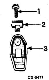
Rocker Arm Assembly
Individually mounted rocker arms are retained by
flange head retaining bolts and pivot balls, Figure 118. All
parts must be retained in the same order as they were on the
engine.
Clean all parts with a good cleaning solvent and use
compressed air to clean out the oil passages in the rocker
arms.
Fig. 118
1.
Retaining bolt
3.
Rocker arm
2.
Pivot ball
Inspect the pivot surface of each rocker arm and
pivot ball and replace any parts which are scuffed, pitted or
excessively worn. Inspect the valve stem contact surface of
each rocker arm and replace any rocker arm which is deeply
pitted. Inspect the rocker arm retaining bolts for excessive
wear or looseness in the cylinder head: replace if condition
exists.
Push Rods
The push rods are hollow and serve as oil galleries to
lubricate each individual rocker arm assembly. Prior to
installation the push rods should be cleaned thoroughly and
inspected for wear and deposits which may restrict the flow of
oil to the rocker arm assemblies.
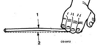
Check all valve lifter push rods for straightness by
rolling on a flat surface, Figure 119
Fig. 119 Checking Push Rod for Straightness
1.
Bent valve lifter rod
2.
Flat surface
CGES-210 Page 43
PRINTED IN UNITED STATES OF AMERICA
|