|
| |
ENGINE DIVISION SERVICE MANUAL
TM 5-4210-230-14&P-1
ENGINE
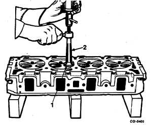
Inspect the exhaust valve seat inserts for looseness,
burned or cracked condition. Use SE-1951 valve insert
remover, Figure 111, to remove defective inserts. Position the
remover collet into the insert and turn the coned screw out to
expand the collet jaws, thus providing a firm grip under the
insert ring. Use a slide hammer to remove the insert.
Fig. 111 Pulling Exhaust Valve Insert with SE-1951 Remover
1.
Exhaust valve insert
2.
Valve insert
remover
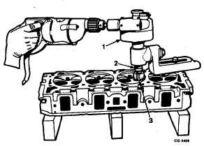
Prior to seat reconditioning, it is desirable to clean
the seats in order to expose any cracks or other conditions
likely to promote valve failure. Such inspection is particularly
important in engines equipped with hard seat inserts; cracked
or loose inserts are not uncommon and are usually caused by
improper installation. Good practice requires that the insert
counterbore in the cylinder head be machined prior to insert
installation, Figure 112. Cutters are available to dress both
the bottom and circumferential surfaces, but regardless of the
method, the bottom of the counterbore must be square to
assure good seating of the insert.
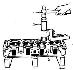
Before installing inserts they should be thoroughly
chilled with dry ice or other means to facilitate their installation
in the cylinder head. Use the installer tool, Figure 113, from
the counterbore tool set'SE-1797. Valve seat inserts supplied
for service are standard size, .015" oversize and .030"
oversize.
Fig. 112
1.
Cutter drive unit
2.
Drive shaft
3.
Cutter
Fig. 113 Using Insert Installer from Counterbore Tool Set SE-
1797 for Installing Inserts in Cylinder Head
1.
Hammer
3.
Seat
2.
Driver
The valve seats "A" and "B" in the cylinder head,
Figure 114, must also be ground true to the angles and width
shown in the specifications section. If the seat is wider than
specified, it
CGES-210 Page 41
PRINTED IN UNITED STATES OF AMERICA
|