|
| |
ENGINE DIVISION SERVICE MANUAL
TM 5-4210-230-14&P-1
ENGINE
Remove all guides that exceed wear limitations using
SE-1722 valve guide remover. All guides must be driven from
the combustion chamber side through the top of the head as
shown in Figure 107.
NOTE:
Support blocks used for removing valve
guides should be 9" long x 3-5/8" high x 1-
5/8" thick rectangular hardwood blocks.
These blocks should not be used for
installation of valve guides.
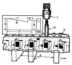
Turn the cylinder head over with the top side up on
the wood support blocks positioned in the press. Install the
valve guides from the top side of the cylinder head using SE-
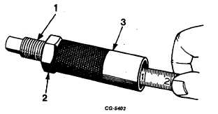
1943 valve guide installer, Figure 109. The tool is designed to
install both valve guides. This can be accomplished by
adjusting the installer screw in the body to a depth that is
equivalent to the specified height that guides are to be
installed above the head. Figure 109 illustrates the method to
be used when adjusting the installer for specified guide height.
Press the guides in until the installer rests firmly on top of the
cylinder head, thus maintaining proper spacing.
NOTE:
Guides
should
be
lubricated
with
a
mixture of light engine oil and white lead
upon installation. Clean away any excess
lubricants.
Fig. 108 Installing Valve Guides with SE-1943 Installer and
Adaptor
1.
Press m
6.
9°
2.
Installer
7.
9"
3.
Cylinder head
8.
11/2
4.
Support Blocks
9.
31/2"
5.
4 1/8
10. 11/2"
NOTE:
Support blocks for installing valve guides
can be made locally to the dimensions
shown in the insert on Figure 108.
Fig. 109 Adjusting Valve Guide Installer SE-1943 for Proper
Height
1.
Adjusting screw
3. Body
2.
Locknut
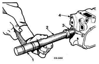
After guides are installed, insert SE-2215 reamer in
the guides to see that they have not been distorted during
installation and to remove any burrs.
Cylinder head core plugs should not be disturbed
unless evidence of leakage exists. Remove and install plugs
as inspection warrants. The plugs can be removed by drilling
a small hole in the center of the plug and with a suitable pry or
screwdriver, remove the plug from its bore. To install a new
plug, coat the outer edge with a suitable nonhardening sealing
compound and with installer SE1945 and driving handle SE-
1581-lB, install plug flush with bottom edge of chamfer in
cylinder head, Figure 110.
Fig. 110 Installing Cylinder Head Core Plugs Using Installer
SE-1945 and Driver Handle SE-1581-1B
1.
Hammer
4.
Cylinder head
2.
Driver handle
5.
Core plug
3.
Installer
CGES-210 Page 40
PRINTED IN UNITED STATES OF AMERICA
|