|
| |
ENGINE DIVISION SERVICE MANUAL
TM 5-4210-230-14&P-1
ENGINE
Inspect the valve springs for proper tension as
outlined in specifications. Any evidence of wear, cracks or
permanent sets will require replacement. SE-2241 spring
tester, Figure 104, or similar tool can be used to check
tension.
Inspect valve locks for excessive wear and replace in
pairs as required. Rotate the Roto-Coil assemblies and
replace if any wear or irregularities are noted. Note
particularly if the Roto-Coil is bound up or feels gritty.
Remove SE-1939 Holding Fixture (if installed) and
position the cylinder head with combustion chamber facing
upward on support blocks, Figure 108. This preparation is
done for valve guide removal.
Check the valve guide bore dimensions (see
specifications). Prior to inspection it is necessary to clean
guides. There are many commercially available wire brushes
and scrapers, Figure 105, that clean guides very satisfactorily.
Similarly, there are various instruments for measuring the
guide bores small-bore gauge SE-2506, plug gauges, etc.,
Figure 106. Plug gauges of the "go" and "no-go" type are most
popular because of the facility with which guides can be
checked. However, there are two undesirable guide
conditions which are difficult to check with gauges of this type:
elliptical or egg-shaped bore wear and bell-mouthing at the
port of the guide. Careful guide inspection will detect egg-
shaped wear while careful use of the "no-go" gauge will tend
to show the degree of bell-mouthing. Replacement is
recommended for guides having bore diameters beyond the
recommended limit or which are bell-mouthed more than
.0005" or which show egg-shaped wear. Excessive guide
clearance prevents adequate cooling of the valve through the
guide and also allows deposits to tilt or tip the valve which
may cause valve breakage at high engine speed. These
conditions tend to prevent good seating and promote leakage
across the valve face. Excessive guide clearance also affects
the proper lubrication of the valve stem.
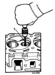
Fig. 105 Valve Guide Cleaning Tool
1. Cleaning tool
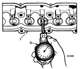
Fig. 106 Checking Guide Bore Using Gauge SE-2506
1.
Cylinder head
3.
Bore gauge
2.
Valve guide
Replacement guides are designed to give proper
clearance when installed in the cylinder head. Reaming is not
required but care must be taken to see that-the ends of the
guides are not burred during installation.
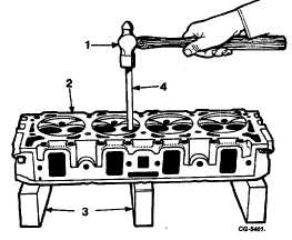
Fig. 107 Removing Valve Guides with SE-1722
1. Hammer
3. Support blocks
2. Cylinder head
4. Remover
CGES-210 Page 39
PRINTED IN UNITED STATES OF AMERICA
|